 Having accurately calibrated equipment here in the DuplexerRepair labs is a must, but sending instruments out to have them calibrated so that we know we’re calibrating and tuning your equipment accurately is very expensive. It also takes the equipment out of service if it has to be sent to an outside lab. Knowing that the ideal solution to keeping the equipment in service, accurately calibrated, and controlling costs would be to have an accurate in-house frequency standard, we decided to explore options such as calibrated rubidium oscillators, cesium driven units, etc.
Rubidium and cesium units have a few disadvantages. First is the cost. They can be very expensive, on the order of several $K for a new one. Second, they have to be re-calibrated periodically due to the natural aging of the oscillator devices. The ongoing cost and the uncertainty between calibrations makes them even less appealing. The solution we were looking for needed to be a combination of:
- Accuracy
- Reliability
- Affordability
- Availability
After much research, the decision was made to go with a GPS Disciplined Oscillator (GPSDO) system. Such a system, as the name implies, utilizes signals from the GPS satellites to precisely control a local oscillator. Each of the GPS satellites in operation are equipped with cesium and/or rubidium clocks and timing circuits. These are in turn all synchronized to the National Institute of Standards and Technology (NIST) cesium clock, which is considered the standard for time and oscillator frequency accuracy in the U.S. By knowing the maximum levels of uncertainty (error) of each device in this chain, it is possible to create a reference system for use in the lab which is traceable all the way back to the NIST. The maximum error in this chain is small — very, very small. We’re talking down to a fraction of a billionth of a second variability. When you convert that time error to a frequency error, it is equally small. It’s much smaller than the level of accuracy required for communications equipment and the manufacturer calibration standards for the equipment we use here in the lab to work on that equipment. The next question was whether to purchase a ready-built system or build it in-house. After much consideration, the decision was made to just put one together right here in the lab using readily available, affordable modules and devices, and design and build any additional components needed for the system.
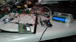
Our GPSDO system, as seen in the photo as it was being assembled and tested here on one of the lab benches, consists of essentially four subassemblies, three of which are off-the-shelf items, and one module/board which was created right here in the lab:
- Ublox Neo-M7M GPS Receiver module
- Arduino Uno module
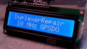
- 16×2 LCD Display module
- Custom designed signal buffering/conditioning board
Once all of the off-the-shelf items were in hand, the task of designing and refining the special buffer board which takes the
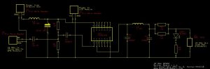
oscillator output from the GPS module (a square wave) and conditions and converts it to a usable sine wave at a very specific frequency took about a week (squeezing it in between other work.) This buffer board also provides impedance matching so that it can be connected to the instruments in the lab as a frequency standard, phase synchronization device, and calibration reference for radio equipment, frequency counters, and other instruments. Our final working prototype is not exactly the most aesthetically attractive looking thing in the world, but it sure does work well. How well? A good example can be seen in the following photograph showing that the IFR (running on the GPSDO system as a 10 MHz reference oscillator) indicates that WWV’s 15 MHz signal to be 15.000000 MHz with an error of 0.0 Hz.
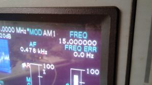
Since we can only see one decimal place beyond the Hz digit in this example, the fact that the 1/10 of a Hz digit is rounding to the digit “0” means the value the IFR is coming up with must be in the range of -0.05 and +0.04 Hz, which equals a calculated maximum error of +/- 0.05 Hz. In the case of our 15 MHz frequency (15,000,000 Hz) that’s equivalent to an error of 0.00333 PPM (or 3.33 PPB, depending on which reference you prefer.) That is way better than the level of accuracy required for communications work. As an example, the FCC says that in land mobile radio equipment, the permissible carrier frequency error for a fixed transmitter operation in the range of 50-450 MHz is 5.0 PPM. Do a little math and you’ll see that our GPSDO has the IFR operating at roughly 1,500 times the level of accuracy required by the FCC rules. Sweet! Even sweeter is the fact that — unlike a rubidium frequency standard which has to be sent off for calibration once a year or so — our GPSDO is essentially updating its own calibration several times a second by constantly receiving the GPS signals and synchronizing itself. With an active gain GPS antenna attached, it rarely indicates being locked on less than 10 satellites simultaneously. It only takes four satellites to achieve a super-accurate “lock” but ours typically registers being locked on 11 and even 12 satellites. Did we mention that is with the antenna still inside the lab? Although it appears quite unnecessary, in the interest of maintaining the best lock and avoiding any potential interference to the GPS performance from equipment running here in the lab, we’re going to be installing an active, weatherproof, marine grade GPS antenna in an elevated position outside the lab. Another benefit of this GPSDO system is the fact it can achieve an accurate frequency lock in less than three seconds of power-up; whereas, rubidium standards employ temperature compensated ovens and typically have to be powered up for several hours for their oscillators to warm up before they stabilize and can be used as a reliable lab reference.
The icing on the cake in this recipe is the affordability of the project. Here’s a rough breakdown of the cost of creating this:
$15.30 — uBlox Neo-M7M GPS Module
$19.48 — Active GPS antenna and necessary adapters and cables
$5.45 — Arduino Uno (“knock-off”/compatible 3rd party clone)
$8.79 — 16×2 LCD Display with I2C interface module
>$10.00 — estimated cost of perf board, electronic components, etc. to build prototype “buffer board”
——————————————————
$59.02 — estimated final cost
That’s less than the one-way shipping cost of sending just the IFR analyzer off for calibration (and don’t even ask the actual cost of the calibration service — it’s astronomical.) With a hyper-accurate 0.00333 PPM frequency reference in-house, that’s exactly where the calibration work on our instruments will be done if/when needed.
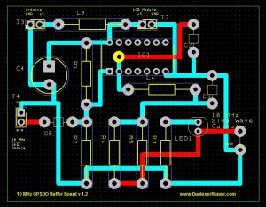
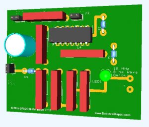
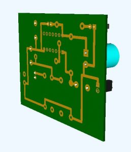
A rework of the schematic and accompanying PCB layout have now been completed and we’ll soon be fabricating a nicely laid-out version 1.2 of the Buffer Board. Once we’ve fully assembled and tested that prototype board, we’re considering having several of the boards manufactured so that others who are interested in putting together a similar system can simply purchase one of our buffer boards and the parts to populate it (which we might offer in a kit form.) Estimated time to solder all the components is roughly 30 minutes to an hour, depending on how well versed you are with a soldering iron.) There might be a version 2.0 board in the works as well — using SMD components to further reduce the cost, board size, power consumption, and to reduce the amount of RF emission.
Stay tuned! (Pun only slightly intended.)