At DuplexerRepair.com, we convert a lot of the Decibel Products / dbSpectra DB4062 VHF from higher frequency VHF models (“-C” model designator, 154-174 MHz range) to 2-Meter Ham / Amateur Radio operating range (“-B” model designator, 143-156 MHz range.)
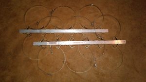
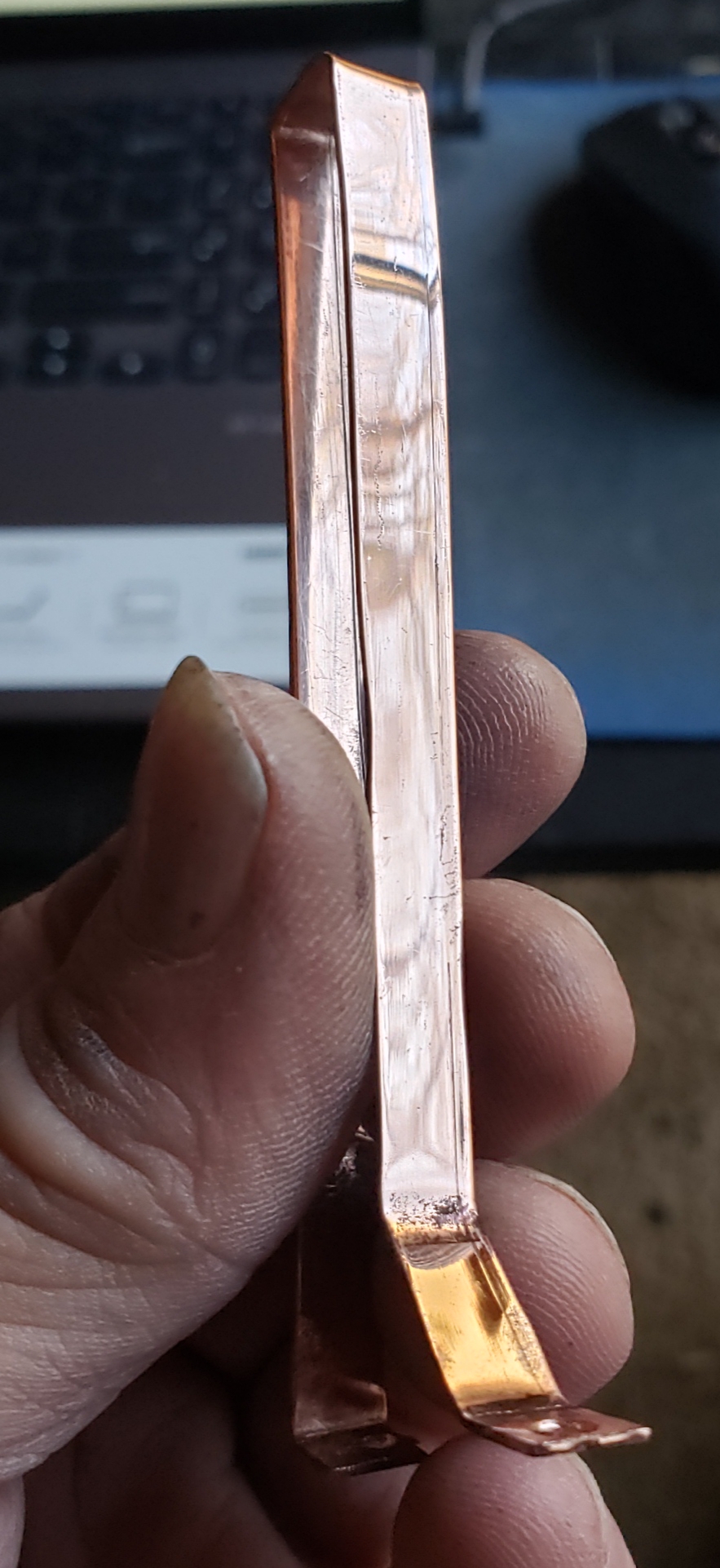
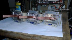
A finished, hand crafted “-B” loop, ready for installation in a loop assembly for conversion to Ham/Amateur Radio operating range.
Conversion to the “-B” model requires replacing half of the loops (2 loops in a DB4060 set, and three loops in a DB4062 set) with loops of the proper length. The required conversion loops are hand-made from stock, 30-mil copper right here in the labs of DuplexerRepair.
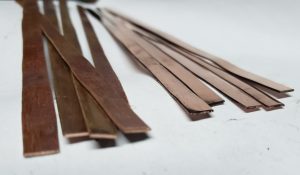
Starting with the copper stock, the copper is cut to proper size, then meticulously cleaned and polished. Then, the copper strips have to be marked, drilled, and properly shaped.
30-mil copper cut to the proper length and width for turning into -B conversion loops.
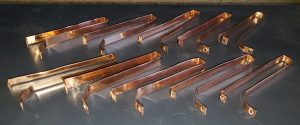
We just thought you might like to see some photos of how they look when they’re finished and ready to go into loop assemblies. What you are seeing in these photos is a batch which was just finished this morning in order to fill a couple of pending orders/jobs.
The latest batch of hand-crafted loops, ready for use.
This is a time and labor intensive process, but it’s worth it in the end, resulting in the duplexers actually performing to (usually better than) factory specifications for the -B model.
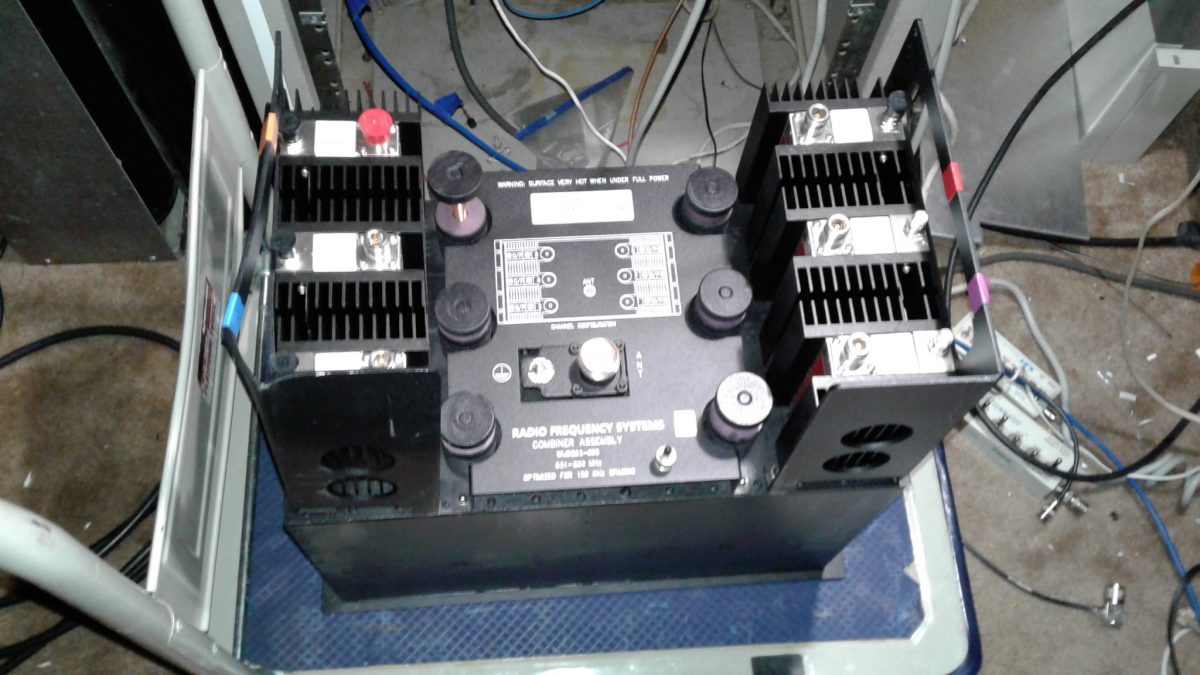
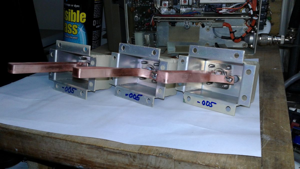
At DuplexerRepair.com, all tuning and service/repair jobs are taken seriously, but now and then an especially interesting item rolls into the lab for service. In this instance it was an RFS Corporation model WIJD862-05SSP 6-Channel, 800 MHz combiner. After retuning for a
change of frequencies/channel for the client, this 83 pound beast is nicely outperforming the factory specifications. It’s a rather impressive piece of communications hardware, although I have found RFS equipment to perform well in every instance.
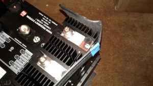
Even after taking a good lick, it performs as expected — and better
This one actually survived an apparent drop or impact to one corner of the box during shipment which had to be a pretty good “lick,” because it totally
The isolator mounting flange/handle showed evidence of a pretty good drop or hit during shipping, but the performance is still excellent.
bent one of the heavy gauge metal isolator mounting flanges (which doubles as a lifting handle.) Even after taking this hit, the combiner is performing great — better than factory specifications, in fact.
If you’d like to see for yourself just how well this thing performs, just click on this link to view the performance report which includes network analyzer graphs and photos of the unit and the mechanical damage which occurred during shipping.
Tuning one of these takes considerably longer than even a multi-cavity duplexer assembly, and it’s much more involved. But it’s actually a blast to do and it sure feels nice when you finish the work and see just how great it performs. Only thing is: after you move this heavy thing around it’s a bit tempting to add a line item to the client’s invoice — the cost of a trip to a chiropractor or a masseuse.
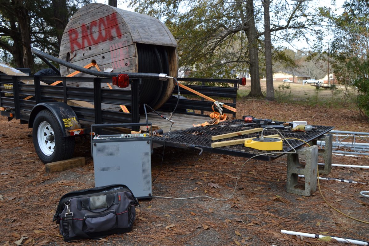
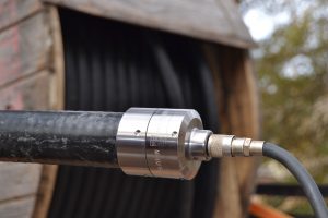
RFS NF-LCF158-D01 installation on LCF158 1-5/8″ Cellflex corrugated coaxial cable
The female N-connector needed to be installed and tested prior to this 550′ piece of RFS LCF158 1-5/8″ corrugated coaxial feedline being hoisted up a new tower which is currently being erected. The installation of the connector went well and the connector/cable combination sweep-tests at approximately 546 feet which is more than close enough to tell us that the connector installation and the cable checks good and is ready to be hoisted up the tower and put into use. For a lot more details, photos, and technical information regarding the installation of the RFS “D01” series connectors on LCF158, you can click on this link.
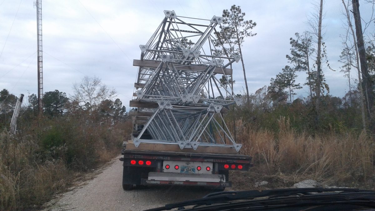
After about a year of helping a client with our part of the planning, preparations, and procurement of antennas, feedlines, hardware, etc. for the “Swap and Drop” replacement of the approximately 450′ Auburn communications tower, it’s about to start going up. The tower sections were delivered this morning, but due to rain in the forecast and a delay in the delivery of some of the guy wire hardware and other materials, it looks as if the first section won’t be going up until next week. It is anticipated that erection of the new tower will take about ten days. This one is going to be cool to watch, since the gin pole system will be rigged in “Chicago Boom” fashion, which means that once it’s up and the gin pole/boom system is at the top of the new tower, the old tower will be dismantled and lowered to the ground by literally reaching across from the new one, similar to a tower-mounted crane, which is essentially what it amounts to. Can’t wait to see this shiny piece of hardware go up, although seeing the old tower — built back in the 1960’s — being dismantled and hauled away has a bittersweet feeling to it. I suppose that’s a “broadcast and radio guy” sort of thing. There’s just something nostalgic about some long-standing towers which have provided many, many years of service, weathered all sorts of storms… hmmm… kind of makes me wish I could have the old one reassembled in my back yard. 😉
The db Products / dbSpectra DB4060 and DB4062 duplexers are awesome in terms of performance for 2 Meter repeaters. That is… if they are built as or converted to true “-B” models (and they are in good overall condition.)
There have been numerous different “cheats” and workarounds published on the web on how to use a set of DB Products (now DBSpectra) DB4060 and DB4062 duplexers which were manufactured for frequencies other than the Amateur Radio / Ham band on 2 Meter ham repeaters. We’ve probably seen all the same “tricks” you have seen, and by and large they are all compromise solutions which don’t result in very good performance and — in some cases — can result in costly damage to the duplexers and radio equipment, not to mention frustrating down-time.
Let’s get real…
The bottom line is this: if the loop assemblies (more specifically the copper loops inside the enclosures) are not correct, they won’t perform to factory specifications of a DB4060 (4-cavity) or DB4062 (6-cavity model) with the “-B” model suffix. The “-B” model is a 143-156 MHz duplexer; however, most of what hams find for sale or salvage is the “-C” model, which was/is manufactured for 154-174 MHz operation. Trying to use a non-converted “-C” set for 2 Meter, 144-148 MHz purposes is a very good way to end up pulling your hair out. They won’t provide the factory-specification Return Loss (SWR), Insertion Loss, or the notching/isolation performance which Amateur Radio repeater owners are truly looking for. But have no fear — they can be converted to a -B set and meet or exceed factory performance specifications.
DuplexerRepair.com offers multiple solutions for converting DB4060 and DB4062 duplexers to true “-B” models.
Depending on your budget, location, skills, and available resources, the following options are available for converting a set to a -B model:
Bring (or ship) the whole set to DuplexerRepair.com and we’ll do the conversion, inspect the cavities, completely overhaul the internal workings of the cavities if needed, do any other needed repairs, and convert the loop assemblies. When we’re done with them, you will have a set of great working “-B” duplexers, tuned and ready for use on your repeater.
If you have someone local who can do the tuning for your, you can just send us your loop assemblies and we’ll convert them (including testing the trimmer capacitors and replacing any which have failed or show signs of impending failure.) When you get the loop enclosures back, just install them on the proper cavities with the proper cables and have someone tune them for you (or do it yourself, if you have the proper equipment and skills.)
If you are VERY comfortable with your soldering skills (or have someone close by who is), we can sell you a set of custom-made copper loops, which — when installed in place of the original loops in your duplexer — will
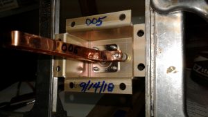
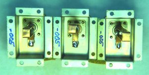
Loop assemblies converted to “-005” loops by DuplexerRepair.com
convert the set to a “-B” model. Note that we highly emphasize the soldering skills issue, here, because the precision trimmer capacitors used in these duplexers are extremely sensitive to heat — including too much heat during soldering. Those capacitors are expensive, and it’s very easy to destroy one or more during loop replacement if you’re not well-versed in soldering or using the wrong equipment and tools. Our DB4060 and DB4062
Another view of loop enclosures which have been converted to -005 enclosures in the DuplexerRepair.com labs.
replacement/conversion loops are made by hand right here in the lab. Depending on whether or not we have some already made up and ready in our inventory, it might take us a few days to custom fabricate the loops and ship them to you.
If you are interested in purchasing a set of replacement/conversion loops, sending us your loop enclosures for conversion, or bringing/sending your DB4060 or DB4062 duplexer set to us for conversion, just contact DuplexerRepair.com to make arrangements or to get more information.
“How do I know if my set actually needs conversion to a ‘-B’ model?”
First, if your duplexer set has anything other than a “-B” in the model designator, it definitely is not a set which was originally built for 2-Meter ham use. If you are still not sure, there are two dead giveaways that your set needs conversion:
The cables BETWEEN the low pass cavities should be 10-1/2″ long (measured tip-to-tip of the N-connector center pins.) All other cables in the set (between the high pass cavities, and on both sides of the antenna TEE-connector to both branches) should measure exactly 10″ in length.
The loop assemblies on the LOW PASS side should be “-004” assemblies, and the HIGH PASS cavities should all have “-005” loop assemblies. The
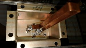
Factory “004” loop enclosure, identifiable by the penned “004” on the bottom of the housing’s mounting flange.
three digit number denotes which length copper loops were installed at the factory, thereby determining the pass and reject frequency range for the cavity/loop assembly combination.
Herein lies the catch: dbSpectra (formerly db Products) starting stamping the assembly numbers on the outside of the mounting flanges of the enclosures at some point, but almost every set we’ve seen here in the lab pre-date that practice. On non-stamped enclosures, you have to remove the cabling from the loop enclosure, remove the eight screws used to attach the enclosure to the top of the cavity, then look at the underside of the enclosure. They marked them at the factory (sometimes with a permanent “Sharpie” type marker, sometimes with a pencil, and sometimes by just scratching the number into the metal. You will find either the number “-003,” “-004,” or “-005” marked on it. In order for it to be a “-B” set of duplexers, it has to have -004 assemblies on the low pass cavities, and -005 assemblies on the high pass side. Anything other than that means the set definitely needs to be converted.
A little more information regarding our custom-made replacement/conversion loops
The custom-made replacement/conversion loops we make here at DuplexerRepair.com are painstakingly hand-made from high quality, 30-mil copper. They are measured and cut by hand, drilled, de-burred, shaped,
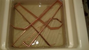
Custom-made replacement/conversion loops being ultrasonically cleaned prior to polishing and installation in the loop enclosures.
ultrasonically cleaned, and polished before installation in the loop enclosure. When we do the full loop assembly conversion job, we clearly mark the new designator on the underside of the flange, and typically label the outside of the enclosure as well with the conversion date and the new designation number. If we replaced the capacitors in the loop, we like to mark that on the outside as well, including the date the capacitor was replaced. Repeated failure of capacitors — especially in the same cavity position in a set — is a sign that something else in the repeater/transmitter system may be occurring which needs to be corrected.
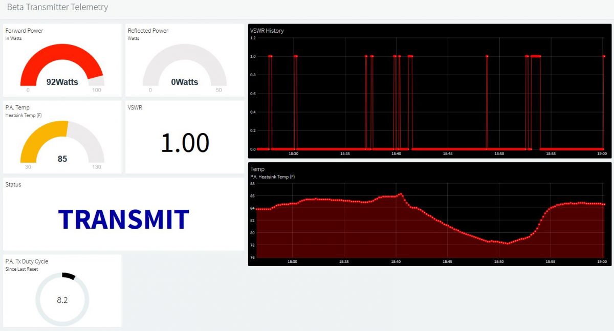
Several additions and modifications have been made to the development/beta version of this transmitter telemetry system over the
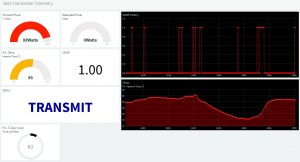
The latest look and feel of the online telemetry dashboard, developed as of the beta version 1.4 Arduino Sketch code.
past couple of days. Keyline status monitoring has been added to the circuitry and code (indicating whether the transmitter is in “STANDBY” or “TRANSMIT” mode) which can be seen in real time on the updated dashboard, which has a few added features, including up to 24 hour graphing of the P.A. heatsink temperature, and P.A. duty cycle percentage display. As I mentioned before, this is a “work in progress” and the imagination is about the only limit to what I can build into this telemetry system.
————————————————–
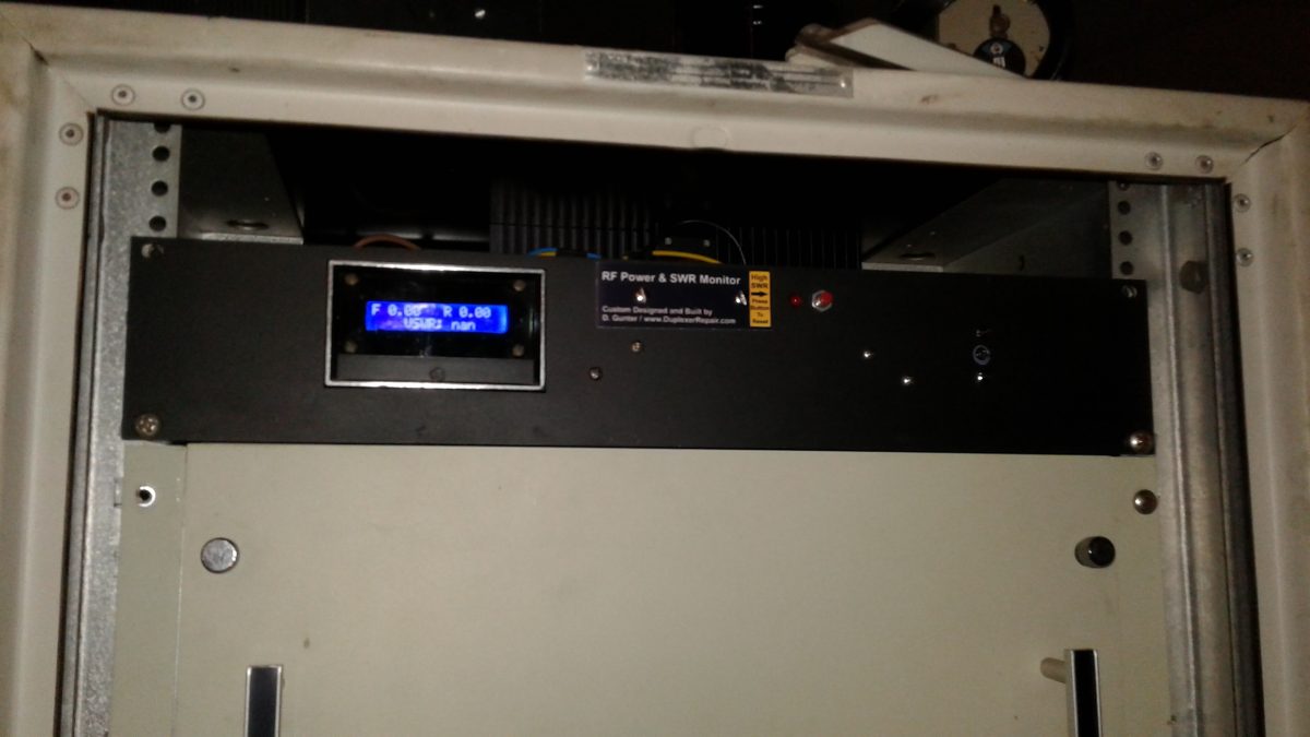
[Original post] Having gotten the Power & SWR Monitor Panel with LCD display to a state that it’s ready to operate permanently on one of the paging transmitters
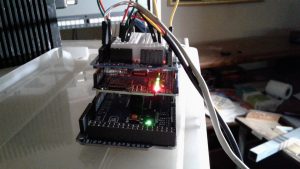
Arduino Mega 2560, topped with an Ethernet shield, along with a Prototyping board with breadboard for convenient modifications, additions, etc.
owned by a client, I’ve already begun developing the next generation of the project: an IoT based monitoring system which provides real-time monitoring of system performance.
This generation of the project utilizes an Ethernet shield running on an Arduino Mega development board. It also has the added feature of temperature monitoring. The thermal probe is strapped to the back of the P.A. heatsink assembly for now. I plan to test locating the thermal probe inside the P.A. final stage cavity, but it remains to be seen whether the high level of RF inside the cavity may interfere with the circuitry which is actually located inside the working end of the probe.
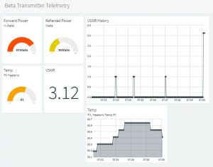
Screenshot of the online telemetry as it appeared during an intentionally created high SWR event (transmission line disconnected.) VSWR calculated as 3.12:1. (Note: the dashboard no longer looks exactly like this — see photo posted in 11/24/18 update above for the latest version.)
The system monitors and will remotely display forward RF power, reflected RF power, SWR/VSWR, and the heatsink temperature. I am considering adding monitoring of the “key” line. The purpose of doing that would be to be able to remotely determine whether a system malfunction (pages not being transmitted) was related to problems with the linking receiver system (which would result in no transmit “keying” of the other components in the system), keying with no or low P.A. output (most likely P.A. or exciter failure or malfunction), or high SWR (antenna or transmission line issues.) The latter two are already covered, but being able to narrow down a link receiver radio issue before even packing up for a service call could be very useful (one of those radios weighs about five pounds… if you’re familiar with Glenayre/Quintron equipment, then we don’t even need to talk about how much one of the Glenayre or Quintron power amplifiers weighs!)
Now, it’s time for coffee while I sit and ponder what cool things to do to this creation next. It is truly a work in progress.
This video demonstration shows the custom-built, Arduino-based RF Power & VSWR Monitoring/Alarm system which I recently built as part of my engineering work for a client who owns a multi-site paging company and uses Glenayre and Quintron paging systems. They are great systems — built like tanks and extremely reliable. We had a few of their Power Monitor panels sitting around, but despite much searching, nobody seems to have the documentation, schematics, wiring diagrams, etc. on these power monitors, which haven’t been manufactured in many years. To wit, I decided to just “gut” the thing and use the chassis and the old meter bezel/lens and build one that does everything I wanted it to. While this project was originally intended with the client’s Quintron and Glenayre paging transmitters in mind, the monitor/alarm system is just as usable in other transmitter systems or repeaters — it’s really just a matter of having an RF power sensor of the right type (proper operating frequency range and output voltage range.)
Starting with an Arduino Uno R3 development board, a dbProducts power sensor, a 16×2 LCD display, I went to work building this RF Power & SWR
Monitor/Alarm system, which constantly measures the transmitter’s forward and reflected power in Watts, and uses an algorithm to precisely calculate the VSWR, all of which is in turn displayed on the front panel.
In the event of a high SWR event, the LCD display shows the actual VSWR and an audible alarm is activated. In addition, an SWR alarm LED turns on, which remains lit until a momentary contact button is pressed, resetting the alarm condition. I wrote the Arduino IDE sketch code to “latch” the LED so that in the event of a temporary high SWR event (ice on the antenna, for example) the system can continue to update and display real-time power and SWR readings but there will be a visible indication on the front panel that a temporary high SWR issue occurred.
The above video shows the system running my v2.4 Arduino sketch code. There will be future updates to the code and the hardware, as I intend to add features such as temperature monitoring, remote access/monitoring, automatic alerting of alarm conditions via RF signaling and/or internet linking, etc. I most likely will end up designing and building a custom Arduino “shield” for a much neater, quicker, easier installation and deployment. The main thing is that the first working version of this monitoring/alarm system is now built, installed, operational, and doing everything I originally intended to do.
This initial build has a few cosmetic imperfections, but hey… in the future I’ll use a better grade of paint when “masking off” all but the desired portion of the original lens/bezel assembly to accommodate the actual LCD display size and repainting the front panel to do away with the original labeling, etc. Until then, it does the job, so who cares if it doesn’t look all spit-polished like it was made in a factory (with a price tag to prove it) ?!?!?!
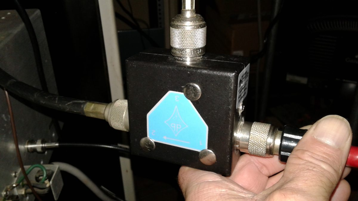
I often get asked “Do I really need to spend the money to purchase an RF isolator and have it tuned for installation on my repeater or transmitter? And, if so, why?” In this video, I demonstrate (and test) a db Products (Decibel Products) DB4613-1A isolator on a 100 Watt paging system, showing how the isolator protects the P.A. from high SWR (even full reflected power) in the event of broken, damaged, shorted, or disconnected feedline, damaged or iced-over antenna, etc. Just take five or six minutes to watch this video and you’ll fully see for yourself why an isolator is an excellent investment for your system. DuplexerRepair.com provides professional, precise tuning and testing of isolators, with quick turnaround and full testing — including a custom report showing the tuning and performance of your isolator when it’s finished.
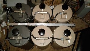
We’ve recently converted a couple of sets of Decibel Products (a/k/a/ dbProducts and dbSpectra) 4-Cavity 4060-WOC-C duplexers to 4062-WOC-B models. Translation:
4062-WOC-B Duplexer built by converting a new set of 4060-WOC-C cavities to “B” models, and overhauling and converting two additional “C” cavities from a failed set, resulting in a great working 6-cavity “B” model with over 100 dB of isolation in each branch.
we’ve converted 4-cavity sets which were built for operation at higher, public safety and commercial frequencies to 6-cavity sets which are optimized for operation in the 2-Meter Amateur Radio / ham frequency bands.
Doing so involves a fair amount of time and work, including total overhaul of each cavity, custom manufacturing of the correct length loops, capacitor replacements, and the building of a new frame for the expanded 6-cavity set, not to mention final tuning and performance testing.
Tuning Plunger Removal, Inspection, and Polishing
After disassembly of the old cavities, one of the many steps in the overhaul and conversion process involves getting the tuning plungers back in good
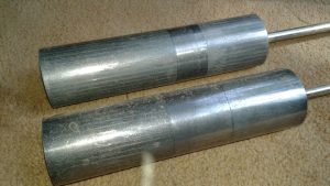
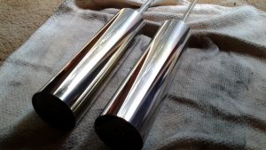
Aged, oxidized tuning plungers BEFORE cleaning and polishing.The same two tuning plungers after careful cleaning and polishing.
shape. As can be seen in these photos showing the plungers before and after the application of some TLC, the difference is more than visible. So is the resulting performance and ability to be accurately tuned (and for that tuning to remain stable.)
Custom Copper Loop Fabrication and Loop Enclosure/Cavity Conversion
In order to obtain the best cavity SWR (lowest insertion loss) along with the maximum branch notching/isolation performance, the copper loops in one
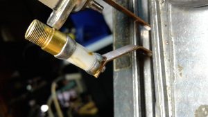
Original capacitor with signs of excessive heating, old flux residue which had not been cleaned off after soldering, etc. This capacitor had failed, causing the set to be taken out of service.New capacitor and custom made loop installed. The enclosure has been relabeled from the original “003” part number to its new, proper “005” designation.
branch of the duplexer assembly have to be replaced with loops of the correct length. At DuplexerRepair.com, we handcraft the replacement copper loops. We start with high quality, 30-mil copper and carefully cut, shape, drill, and polish the replacement loops.
During the installation of the new, replacement loops of proper dimensions for 2-Meter operation, we also replace the trimmer capacitors. This is actually a delicate process, as these capacitors do not tolerate excessive heat. It is quite common for us to discover signs of overheating from the combination of the original capacitor installation, soldering, and RF heating over time (mistuning, high SWR, and lightning will destroy these capacitors pretty easily.)
Frame and Mounting Rail Fabrication / Conversion
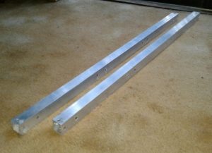
The original 4-cavity frame and mounting rails for assembling the cavities into a set have to be replaced in order to accommodate six cavities. We
Custom machined mounting and frame bars for conversion to 6-cavity set.New custom made rails with cavity braces and clamps installed.
custom machine these from square aluminum tubing.
Reassembly, Cable Harness Inspection and Service, and Final Testing
With all the components overhauled and reassembled using the new frame and mounting rails, each cable, Tee-connector, etc. is inspected and cleaned
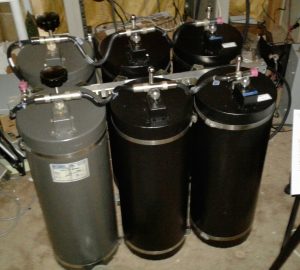
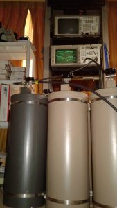
Another 6-cavity 4062-WOC-B set we recently converted, overhauled, and built, reassembled and ready for final tuning and testing.Duplexer assembly being put through final tuning and performance testing and verification. The client gets a complete report of the testing, including the network analyzer graphs showing proof of performance.
or replaced as necessary.
Each cavity is then individually performance tested, followed by connecting each branch as a set and testing it, and finally the entire harness is secured and the entire set undergoes its final tuning and performance testing.
The End Results
A complete conversion, expansion, and overhaul job such as the ones described here, commonly involves between 15 to 20 hours of labor, plus
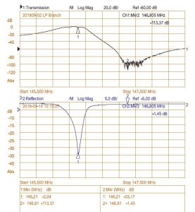
With 113.37 dB of isolation (factory spec is 100 dB or higher) with only 1.45 dB of IL (Insertion Loss (factory spec is 2.2 dB or less), this set is working considerably better than factory specifications. Well worth the investment of time, money, and energy.
materials. It’s not exactly cheap, but the results are worth it. What usually starts out as a 4-cavity 4060 “C” model (not built for factory spec operation in the 2-meter Amateur radio band, and often a set which has failed and been pulled from service) becomes a great working 4062 “B” model — as though it left the factory as a set intended to work to specs in the 2-Meter band. The 4-cavity 4060 models are rated at 80 dB or more of branch isolation; whereas the 4062 6-cavity sets are rated for 100 dB or higher isolation. At the typical 600 KHz “split” used in 2-Meter band, this extra isolation makes a world of difference, especially at transmitter power levels above 40 watts or so, and can be a game-changer when trying to get better performance out of certain repeaters, such as the Yaesu Fusion DR-1/DR-1X series, which tend to have lower receiver selectivity compared to most of the commercial grade repeaters with highly selective physical filtering on the front-end. Very often we deal with duplexers sent to the DuplexerRepair.com labs with complaints of “They worked great for years with our old Mastr II repeater running 40 Watts, but when we bought and installed a new Fusion repeater (or D-Star repeater, DMR machine, etc.) everything went to crap.”
We deal with such all the time. And we’re here to help. Call or contact us if you’re experiencing similar problems. We’ll be delighted to help you get things working the way they should. As they say, “A chain is only as strong as its weakest link.” Duplexers which aren’t up to the task will result in a poor or totally useless repeater setup. It doesn’t have to be that way. We’re here to remedy that.
We have been monitoring the status of a tower in a community south of Opelika which was supposed to have been taken down a while back. This
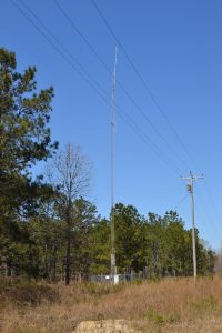
The curving of the tower in this photo is not camera distortion. It really is bowing and bending as bad as it looks.
tower has been (not so affectionately) nicknamed “Uncle Wobbly” because you can watch it precariously sway with the wind. It is also bowing and leaning very badly. All of this is because it only has three of the original guy wires still intact, and only two of those are actually supporting the tower. The guy wires are old and extremely rusted and six of the original nine guys have broken. Two guys remain on the back side of the tower at approximately the 60′ level, and one on the front at approximately the 80′ level.
The guy wire at the front (from the vantage point of the road — and utility lines — is the only top guy remaining, and it’s slack. That “slackness” is actually a good thing in this instance, because with the other two top guys missing, one can venture a pretty accurate guess as to what would happen if someone put much tension on that top/front guy.
Two of the three front guys have been broken for quite some time, and you can see the extremely rusted condition of the guy wires in this photo.
This tower is only about 50 feet from the utility lines running parallel to the road. That has created a seriously hazardous situation. The tower is 110′ tall (including appurtanances.) Obviously, if it falls in the direction it is leaning, there is a high likelihood it will fall across the utility lines and the roadway. This decommissioned tower was slated for dismantling in the Fall of 2017 according to the tower owners, but that work has not yet been done.
We will not be the least bit surprised to get a call at any moment letting us know the tower has completely failed. We also would not be surprised to hear that it damaged the utility lines (and quite possibly the utility pole nearest the tower) and caused interruption of utilities for a lot of folks in the area.


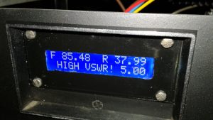 In the event of a high SWR event, the LCD display shows the actual VSWR and an audible alarm is activated. In addition, an SWR alarm LED turns on, which remains lit until a momentary contact button is pressed, resetting the alarm condition. I wrote the Arduino IDE sketch code to “latch” the LED so that in the event of a temporary high SWR event (ice on the antenna, for example) the system
 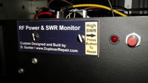 can continue to update and display real-time power and SWR readings but there will be a visible indication on the front panel that a temporary high SWR issue occurred.