This video demonstration shows the custom-built, Arduino-based RF Power & VSWR Monitoring/Alarm system which I recently built as part of my engineering work for a client who owns a multi-site paging company and uses Glenayre and Quintron paging systems. They are great systems — built like tanks and extremely reliable. We had a few of their Power Monitor panels sitting around, but despite much searching, nobody seems to have the documentation, schematics, wiring diagrams, etc. on these power monitors, which haven’t been manufactured in many years. To wit, I decided to just “gut” the thing and use the chassis and the old meter bezel/lens and build one that does everything I wanted it to. While this project was originally intended with the client’s Quintron and Glenayre paging transmitters in mind, the monitor/alarm system is just as usable in other transmitter systems or repeaters — it’s really just a matter of having an RF power sensor of the right type (proper operating frequency range and output voltage range.)
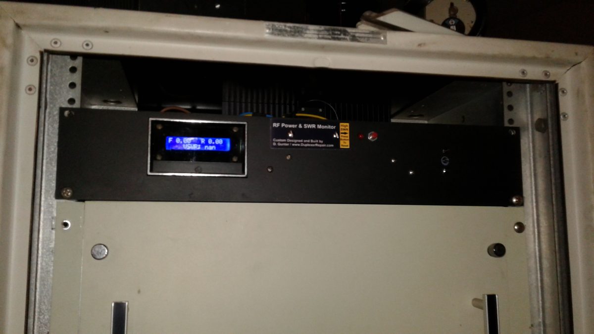
Starting with an Arduino Uno R3 development board, a dbProducts power sensor, a 16×2 LCD display, I went to work building this RF Power & SWR
Monitor/Alarm system, which constantly measures the transmitter’s forward and reflected power in Watts, and uses an algorithm to precisely calculate the VSWR, all of which is in turn displayed on the front panel.
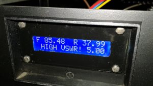
In the event of a high SWR event, the LCD display shows the actual VSWR and an audible alarm is activated. In addition, an SWR alarm LED turns on, which remains lit until a momentary contact button is pressed, resetting the alarm condition. I wrote the Arduino IDE sketch code to “latch” the LED so that in the event of a temporary high SWR event (ice on the antenna, for example) the system can continue to update and display real-time power and SWR readings but there will be a visible indication on the front panel that a temporary high SWR issue occurred.
The above video shows the system running my v2.4 Arduino sketch code. There will be future updates to the code and the hardware, as I intend to add features such as temperature monitoring, remote access/monitoring, automatic alerting of alarm conditions via RF signaling and/or internet linking, etc. I most likely will end up designing and building a custom Arduino “shield” for a much neater, quicker, easier installation and deployment. The main thing is that the first working version of this monitoring/alarm system is now built, installed, operational, and doing everything I originally intended to do.
This initial build has a few cosmetic imperfections, but hey… in the future I’ll use a better grade of paint when “masking off” all but the desired portion of the original lens/bezel assembly to accommodate the actual LCD display size and repainting the front panel to do away with the original labeling, etc. Until then, it does the job, so who cares if it doesn’t look all spit-polished like it was made in a factory (with a price tag to prove it) ?!?!?!
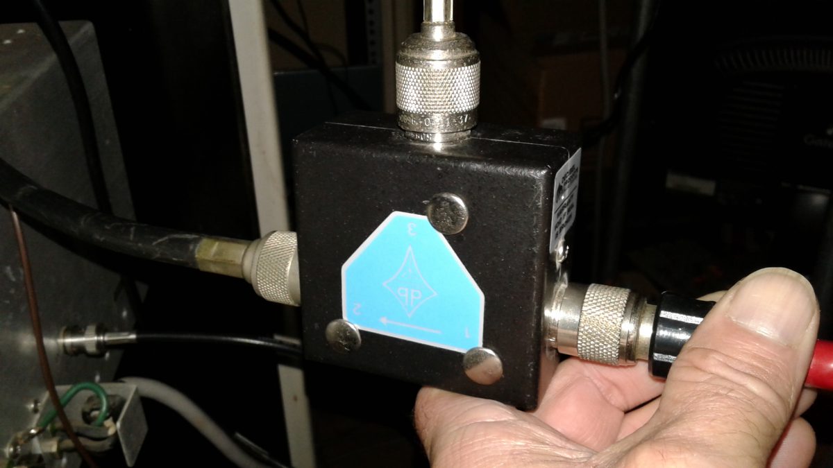
I often get asked “Do I really need to spend the money to purchase an RF isolator and have it tuned for installation on my repeater or transmitter? And, if so, why?” In this video, I demonstrate (and test) a db Products (Decibel Products) DB4613-1A isolator on a 100 Watt paging system, showing how the isolator protects the P.A. from high SWR (even full reflected power) in the event of broken, damaged, shorted, or disconnected feedline, damaged or iced-over antenna, etc. Just take five or six minutes to watch this video and you’ll fully see for yourself why an isolator is an excellent investment for your system. DuplexerRepair.com provides professional, precise tuning and testing of isolators, with quick turnaround and full testing — including a custom report showing the tuning and performance of your isolator when it’s finished.
We’ve recently converted a couple of sets of Decibel Products (a/k/a/ dbProducts and dbSpectra) 4-Cavity 4060-WOC-C duplexers to 4062-WOC-B models. Translation:
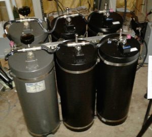
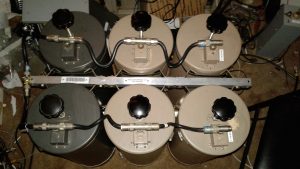
4062-WOC-B Duplexer built by converting a new set of 4060-WOC-C cavities to “B” models, and overhauling and converting two additional “C” cavities from a failed set, resulting in a great working 6-cavity “B” model with over 100 dB of isolation in each branch.
we’ve converted 4-cavity sets which were built for operation at higher, public safety and commercial frequencies to 6-cavity sets which are optimized for operation in the 2-Meter Amateur Radio / ham frequency bands.
Doing so involves a fair amount of time and work, including total overhaul of each cavity, custom manufacturing of the correct length loops, capacitor replacements, and the building of a new frame for the expanded 6-cavity set, not to mention final tuning and performance testing.
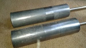
Tuning Plunger Removal, Inspection, and Polishing
After disassembly of the old cavities, one of the many steps in the overhaul and conversion process involves getting the tuning plungers back in good
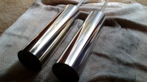
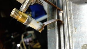
Aged, oxidized tuning plungers BEFORE cleaning and polishing.The same two tuning plungers after careful cleaning and polishing.
shape. As can be seen in these photos showing the plungers before and after the application of some TLC, the difference is more than visible. So is the resulting performance and ability to be accurately tuned (and for that tuning to remain stable.)
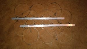
Custom Copper Loop Fabrication and Loop Enclosure/Cavity Conversion
In order to obtain the best cavity SWR (lowest insertion loss) along with the maximum branch notching/isolation performance, the copper loops in one
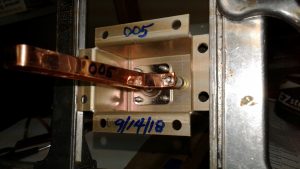
Original capacitor with signs of excessive heating, old flux residue which had not been cleaned off after soldering, etc. This capacitor had failed, causing the set to be taken out of service.New capacitor and custom made loop installed. The enclosure has been relabeled from the original “003” part number to its new, proper “005” designation.
branch of the duplexer assembly have to be replaced with loops of the correct length. At DuplexerRepair.com, we handcraft the replacement copper loops. We start with high quality, 30-mil copper and carefully cut, shape, drill, and polish the replacement loops.
During the installation of the new, replacement loops of proper dimensions for 2-Meter operation, we also replace the trimmer capacitors. This is actually a delicate process, as these capacitors do not tolerate excessive heat. It is quite common for us to discover signs of overheating from the combination of the original capacitor installation, soldering, and RF heating over time (mistuning, high SWR, and lightning will destroy these capacitors pretty easily.)
Frame and Mounting Rail Fabrication / Conversion
The original 4-cavity frame and mounting rails for assembling the cavities into a set have to be replaced in order to accommodate six cavities. We
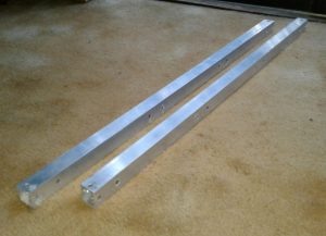
Custom machined mounting and frame bars for conversion to 6-cavity set.New custom made rails with cavity braces and clamps installed.
custom machine these from square aluminum tubing.
Reassembly, Cable Harness Inspection and Service, and Final Testing
With all the components overhauled and reassembled using the new frame and mounting rails, each cable, Tee-connector, etc. is inspected and cleaned
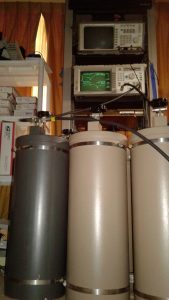
Another 6-cavity 4062-WOC-B set we recently converted, overhauled, and built, reassembled and ready for final tuning and testing.Duplexer assembly being put through final tuning and performance testing and verification. The client gets a complete report of the testing, including the network analyzer graphs showing proof of performance.
or replaced as necessary.
Each cavity is then individually performance tested, followed by connecting each branch as a set and testing it, and finally the entire harness is secured and the entire set undergoes its final tuning and performance testing.
The End Results
A complete conversion, expansion, and overhaul job such as the ones described here, commonly involves between 15 to 20 hours of labor, plus
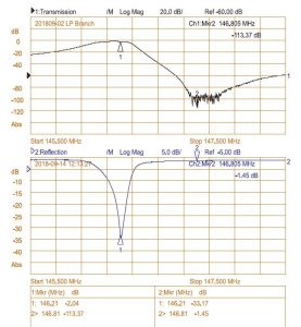
With 113.37 dB of isolation (factory spec is 100 dB or higher) with only 1.45 dB of IL (Insertion Loss (factory spec is 2.2 dB or less), this set is working considerably better than factory specifications. Well worth the investment of time, money, and energy.
materials. It’s not exactly cheap, but the results are worth it. What usually starts out as a 4-cavity 4060 “C” model (not built for factory spec operation in the 2-meter Amateur radio band, and often a set which has failed and been pulled from service) becomes a great working 4062 “B” model — as though it left the factory as a set intended to work to specs in the 2-Meter band. The 4-cavity 4060 models are rated at 80 dB or more of branch isolation; whereas the 4062 6-cavity sets are rated for 100 dB or higher isolation. At the typical 600 KHz “split” used in 2-Meter band, this extra isolation makes a world of difference, especially at transmitter power levels above 40 watts or so, and can be a game-changer when trying to get better performance out of certain repeaters, such as the Yaesu Fusion DR-1/DR-1X series, which tend to have lower receiver selectivity compared to most of the commercial grade repeaters with highly selective physical filtering on the front-end. Very often we deal with duplexers sent to the DuplexerRepair.com labs with complaints of “They worked great for years with our old Mastr II repeater running 40 Watts, but when we bought and installed a new Fusion repeater (or D-Star repeater, DMR machine, etc.) everything went to crap.”
We deal with such all the time. And we’re here to help. Call or contact us if you’re experiencing similar problems. We’ll be delighted to help you get things working the way they should. As they say, “A chain is only as strong as its weakest link.” Duplexers which aren’t up to the task will result in a poor or totally useless repeater setup. It doesn’t have to be that way. We’re here to remedy that.
DuplexerRepair.com is proud to support the Alabama Frequency Coordination and Repeater Advancement Society (AFCRAS), Alabama Amateur Radio’s new ham radio frequency / repeater coordinating entity. AFCRAS was formed by a group of Alabama hams determined to provide the Alabama Amateur Radio enthusiast community the quality and level of service they have been wanting for many years.
Okay, so your old Mastr II was pumping out 50, 75, maybe even 100 Watts with no problem using your trusty old duplexers, but then you installed a shiny new Yaesu Fusion and the proverbial “stuff” hit the fan. Desense galore. Poor sensitivity. User complaints about not being able to carry on a QSO like before — all other factors being equal. You’ve even tried backing the Fusion’s transmit power down to half or less of what you’d been running the old Mastr II’s PA at (or maybe it’s a Motorola) but you still feel as though you’re chasing your tail. I’ve received countless calls, messages, emails, etc. asking for help and advice with this problem. I have known since my very first encounter with a Fusion repeater essentially what the problem was — and various solutions — but today I actually went to the effort to do in-depth technical testing and put some real numbers with it. In all honesty, it’s a bit worse than I had estimated.
The problem is one of “selectivity” — not to be confused with “sensitivity.” Two totally different beasts. My testing does show the sensitivity of the Yausu Fusion to be pretty close to that of the Mastr II and other commercial grade repeater equipment. Where it can’t compare is in selectivity — the ability of the receiver to effectively hear what it’s supposed to while suppressing and not getting swamped by other signals, including (especially) its own transmit frequency. Because the Fusion is much less selective (just how much so you’ll see shortly) you can’t get the same performance out of the Fusion that you were accustomed to with a Mastr II, Motorola, or other truly commercial grade repeater if you try to use the same duplexers. High RF environments such as broadcast transmitter sites or sites with multiple repeaters in operation also become a problem at times with the Fusion; whereas, the old Mastr II and other systems seemed to work okay.
There are a combination of factors which make the receiver in one repeater more or less selective than others. I’ll spare you all the discussions of “Q” and how amplifiers, transistors, etc. actually lose gain at the desired receiver frequency when there’s a lot of RF on frequencies close to it (such as just 600 KHz or so away — typical of ham repeater in the 2-Meter band), but we can’t avoid mentioning it altogether. True, your duplexers help reduce much of the unwanted signals, but they never block 100% of it. The less selective the repeater’s receiver is, the more isolation between the receive and transmit frequencies is needed in the duplexers. By contrast, higher selectivity in the receiver means you can get away with lower “dB” isolation in the duplexers. For example, a Mastr II might work fine at 50 Watts on a high quality set of 4-cavity duplexers, or at 100 Watts on a 6-Cavity set, but the Fusion often takes repeater owners on a not-so-fun journey into desense land at 50 Watts (sometimes 25 Watts) on the same 4-cavity set that the Mastr II had played nicely with in the past. My testing this morning shows how much so.
In order to conduct side-by-side, “apples to apples” testing for comparison purposes, here’s how I set everything up and conducted the tests.
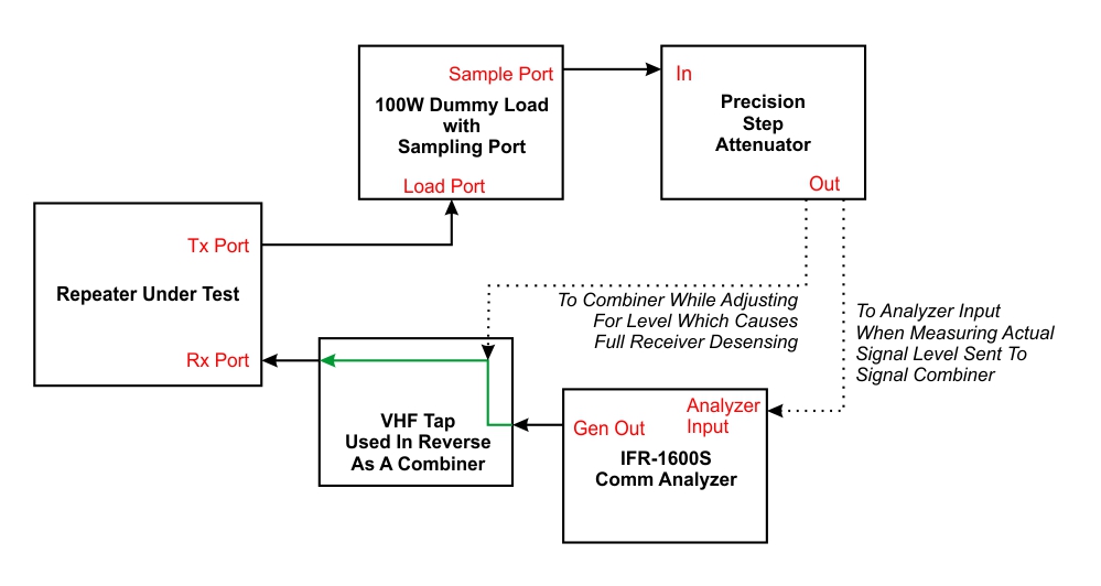
Lab testing setup used for measuring comparative selectivity/desense levels of the Yaesu Fusion DR-1 repeater and a G.E. Mastr II repeater. Tests conducted in VHF/2-Meter band only.
With the setup above, I sent a signal from the IFR-1600S to a combiner, the output of which was in turn routed to the receiver port of the repeater being tested. With the repeater activated, the transmitter output was sent to a 100 Watt dummy load with a reduced level sampling port. The output from that sampling port was then fed to a precision attenuator capable of 1-101 dB attenuation in 1 dB steps, the output of which was combined with the IFR’s output at the second input port of the combiner. This setup allowed me to combine a precisely adjustable amount of the transmitter’s output signal with the desired receive signal. By slowly decreasing the amount of attenuation of the transmit signal allowed into the combiner, I was able to determine how much RF power getting back into the repeater’s receiver would cause desensing. I kept adjusting until the level of the transmit signal going back into the combiner was high enough to cause total desensing of the receiver, meaning that the receiver was unable to discern enough receive signal to even do “cyclic” type key/unkey/key/unkey repeated desensing. The levels I created and measured resulted in total loss of useable reception in the receiver, effectively deafening and shutting down the repeater’s functionality altogether.
It is important to note that this testing does not address the levels at which “white noise” from the transmitter starts causing voice/modulation quality degradation in the repeater’s output. “White noise” and transmitted voice/modulation quality actually start occurring at much lower levels of unwanted transmit RF getting back into the receiver. Such noise gets progressively worse as the level of unwanted signal creeping back into the receiver increases, until it reaches the total desense level. Thus, the amounts of transmit/receive isolation needed (discussed a bit later in this article) in order to have clear, enjoyable QSO’s is actually considerably higher than the levels of rejection/isolation necessary just to avoid total desensing. Don’t use the isolation numbers shown in a bit to be the duplexer performance level you need for your repeater. Rather, the levels discussed in this article allow side-by-side comparison of the selectivity — or ability of each repeater’s receiver to block troublesome, unwanted signals and actually “pick out” and properly demodulate the desired signal.
For testing purposes, I used the following signals:
Rx signal for the repeater: 147.660 MHz, modulated with a 1 KHz audible sine wave tone modulated at 3.0 KHz deviation, and a 123.0 Hz CTCSS tone modulated at a 0.6 KHz level for repeater PL tone operation. Signal level from IFR-1600S set to 0.224 uV for testing of both repeaters.
Tx signal from repeater: 147.060 MHz with no tone generation being added by the repeater.
I chose these particular frequencies and tones for a simple reason: I had recently done a Mastr II repeater conversion for a local amateur radio club using that frequency pair and tones but it was still here in the lab, so a well functioning, properly aligned Mastr II set up as such was readily available. The Yaesu Fusion — being fully programmable and agile — was thus easy to set for identical frequencies and CTCSS operation.
Once I fired up each of the repeaters and had adjusted the level of the transmit signal being intentionally looped back into the receiver so that total desense occurred, I simply disconnected the feedback line from the combiner, which allowed the repeater to start repeating again. The level of the transmit signal coming from the test port of the dummy load and going into the precision attenuator had been measured just before conducting each desense level test. By calculating the resulting level after attenuation and factoring back in the amount of loss presented by the combiner, I was able to calculate the power level (calculated in uW (microwatts) in this instance) and record it. After putting both repeaters through this same test, I had the desired numbers at hand. I already knew that the differences between the Mastr II and Fusion would be noticeable, but they turned out to be a bit more so than I had suspected.
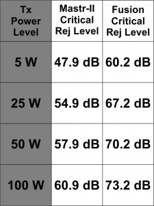
The Fusion repeater would totally desense with unwanted transmitter signal power of 4.77 uW. Contrast that to 80.8 uW that it took for the G.E Mastr II to reach total desense and a lot of things start becoming clearer. This table lists what I’ll refer to as the “Critical Rejection Level” — the amount of transmitter/receiver isolation necessary to prevent total desensing of the receiver for each
Calculated Critical Rejection Levels for comparing the selectivity and desense avoidance capabilities of the Yaesu Fusion DR-1 and the G.E. Mastr II operating in the VHF/2-Meter band.
repeater. The table shows this estimated value calculated for operating each repeater at four power levels: 5, 25, 50, and 100 Watts. Please keep in mind, as mentioned before, that these are not intended to be absolute values to use for specifying duplexer parameters, etc. They are, however, numbers useful for comparison of the selectivity and desense avoidance capabilities of the Fusion and Mastr II. In my overall experience, the amount of transmitter/receiver isolation necessary to actually have relatively white noise-free, clear QSO’s in a repeater are generally 30-40 dB or so greater than what I refer to as the Critical Rejection Level. Shooting the middle and adding 35 dB to the numbers in this table yields numbers very comparable to the actual values of duplexer Tx/Rx isolation I’ve found necessary in real-world practice. I have found that the G.E. Mastr II VHF repeater will typically operate well in a relatively RF-clean environment with 80 dB or greater Tx/Rx isolation up to around 40 Watts, and do well up to 100-125 Watts with at least 100 dB of isolation. By contrast, the Yaesu Fusion is best operated with at least 80 dB of duplexer Tx/Rx isolation at 25 Watts or less, and definitely needs 100 dB or better in order to operate at its 50 Watt transmitter power level or with an outboard power amplifier running between 50 and 100 Watts (again, in a relatively CLEAN RF environment.) Also, these numbers relate only to transmitter/receiver isolation. Operating a repeater in a high-RF environment such as a commercial/broadcast transmitter site will create the need for specialized filtering (such as pre-filters), increased duplexer isolation rating needs, and frequently create intermodulation problems that call for lots of creativity and sometimes end up being impractical to try to overcome. I also have not done extensive testing to see whether or not the Fusion’s transmitter final/PA output is as good as the Mastr II in terms of any harmonics, spurious artifact, etc. in its “Fixed Analog FM” output mode. I suspect that it isn’t, but that’s research for yet another day. For now, suffice it to say that if it’s not, then things get even worse, but for the moment let’s at least imagine that the Fusion and the Mastr II have exactly the same output signal quality.
I am considering repeating these tests using the Fusion in UHF/70CM band and a Mastr II running at the same frequency/band. Almost all complaints I’ve heard regarding the Fusion having desense problems have been in the 2-Meter band, so that was my focus for today’s testing and documentation purposes.
I hope that this information sheds some light on why Fusion repeaters installed as replacements for Mastr II repeaters (and other commercial grade repeaters, such as Motorola equipment) so often create frustration and sleepless nights for so many repeater operators. My hat is off to the folks at Yaesu for creating some exciting, feature-rich repeaters in a price range that put them within the reach of many repeater owners who thought they’d never own a brand-spanking new repeater. Anyone considering purchasing a Fusion just needs to keep in mind that Fusion repeaters are ultimately ham/consumer level equipment and understand that they will not perform as well for analog communications as will a Mastr II or other commercial/professional grade repeater. Installing a Fusion using the same antenna, duplexers, connectors, and other hardware that was previously used with a properly working and aligned commercial grade repeater can and will quickly lead to great frustration unless you’re prepared to make a combination of changes and/or concessions.
 In the event of a high SWR event, the LCD display shows the actual VSWR and an audible alarm is activated. In addition, an SWR alarm LED turns on, which remains lit until a momentary contact button is pressed, resetting the alarm condition. I wrote the Arduino IDE sketch code to “latch” the LED so that in the event of a temporary high SWR event (ice on the antenna, for example) the system
 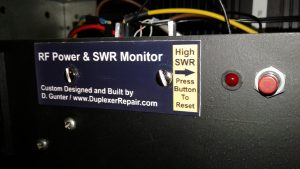 can continue to update and display real-time power and SWR readings but there will be a visible indication on the front panel that a temporary high SWR issue occurred.