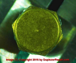
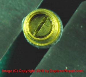
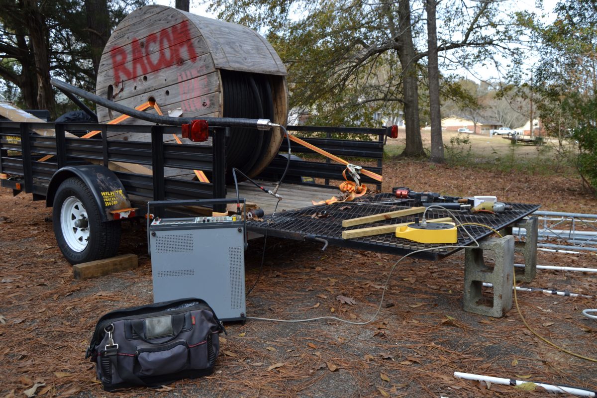
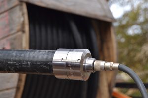
RFS NF-LCF158-D01 installation on LCF158 1-5/8″ Cellflex corrugated coaxial cable
The female N-connector needed to be installed and tested prior to this 550′ piece of RFS LCF158 1-5/8″ corrugated coaxial feedline being hoisted up a new tower which is currently being erected. The installation of the connector went well and the connector/cable combination sweep-tests at approximately 546 feet which is more than close enough to tell us that the connector installation and the cable checks good and is ready to be hoisted up the tower and put into use. For a lot more details, photos, and technical information regarding the installation of the RFS “D01” series connectors on LCF158, you can click on this link.
The db Products / dbSpectra DB4060 and DB4062 duplexers are awesome in terms of performance for 2 Meter repeaters. That is… if they are built as or converted to true “-B” models (and they are in good overall condition.)
There have been numerous different “cheats” and workarounds published on the web on how to use a set of DB Products (now DBSpectra) DB4060 and DB4062 duplexers which were manufactured for frequencies other than the Amateur Radio / Ham band on 2 Meter ham repeaters. We’ve probably seen all the same “tricks” you have seen, and by and large they are all compromise solutions which don’t result in very good performance and — in some cases — can result in costly damage to the duplexers and radio equipment, not to mention frustrating down-time.
Let’s get real…
The bottom line is this: if the loop assemblies (more specifically the copper loops inside the enclosures) are not correct, they won’t perform to factory specifications of a DB4060 (4-cavity) or DB4062 (6-cavity model) with the “-B” model suffix. The “-B” model is a 143-156 MHz duplexer; however, most of what hams find for sale or salvage is the “-C” model, which was/is manufactured for 154-174 MHz operation. Trying to use a non-converted “-C” set for 2 Meter, 144-148 MHz purposes is a very good way to end up pulling your hair out. They won’t provide the factory-specification Return Loss (SWR), Insertion Loss, or the notching/isolation performance which Amateur Radio repeater owners are truly looking for. But have no fear — they can be converted to a -B set and meet or exceed factory performance specifications.
DuplexerRepair.com offers multiple solutions for converting DB4060 and DB4062 duplexers to true “-B” models.
Depending on your budget, location, skills, and available resources, the following options are available for converting a set to a -B model:
Bring (or ship) the whole set to DuplexerRepair.com and we’ll do the conversion, inspect the cavities, completely overhaul the internal workings of the cavities if needed, do any other needed repairs, and convert the loop assemblies. When we’re done with them, you will have a set of great working “-B” duplexers, tuned and ready for use on your repeater.
If you have someone local who can do the tuning for your, you can just send us your loop assemblies and we’ll convert them (including testing the trimmer capacitors and replacing any which have failed or show signs of impending failure.) When you get the loop enclosures back, just install them on the proper cavities with the proper cables and have someone tune them for you (or do it yourself, if you have the proper equipment and skills.)
If you are VERY comfortable with your soldering skills (or have someone close by who is), we can sell you a set of custom-made copper loops, which — when installed in place of the original loops in your duplexer — will
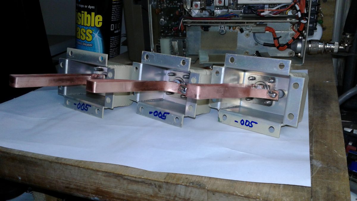
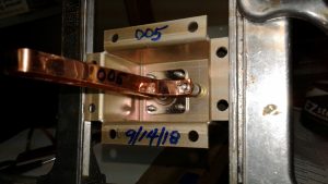
Loop assemblies converted to “-005” loops by DuplexerRepair.com
convert the set to a “-B” model. Note that we highly emphasize the soldering skills issue, here, because the precision trimmer capacitors used in these duplexers are extremely sensitive to heat — including too much heat during soldering. Those capacitors are expensive, and it’s very easy to destroy one or more during loop replacement if you’re not well-versed in soldering or using the wrong equipment and tools. Our DB4060 and DB4062
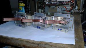
Another view of loop enclosures which have been converted to -005 enclosures in the DuplexerRepair.com labs.
replacement/conversion loops are made by hand right here in the lab. Depending on whether or not we have some already made up and ready in our inventory, it might take us a few days to custom fabricate the loops and ship them to you.
If you are interested in purchasing a set of replacement/conversion loops, sending us your loop enclosures for conversion, or bringing/sending your DB4060 or DB4062 duplexer set to us for conversion, just contact DuplexerRepair.com to make arrangements or to get more information.
“How do I know if my set actually needs conversion to a ‘-B’ model?”
First, if your duplexer set has anything other than a “-B” in the model designator, it definitely is not a set which was originally built for 2-Meter ham use. If you are still not sure, there are two dead giveaways that your set needs conversion:
The cables BETWEEN the low pass cavities should be 10-1/2″ long (measured tip-to-tip of the N-connector center pins.) All other cables in the set (between the high pass cavities, and on both sides of the antenna TEE-connector to both branches) should measure exactly 10″ in length.
The loop assemblies on the LOW PASS side should be “-004” assemblies, and the HIGH PASS cavities should all have “-005” loop assemblies. The
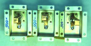
Factory “004” loop enclosure, identifiable by the penned “004” on the bottom of the housing’s mounting flange.
three digit number denotes which length copper loops were installed at the factory, thereby determining the pass and reject frequency range for the cavity/loop assembly combination.
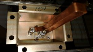
Herein lies the catch: dbSpectra (formerly db Products) starting stamping the assembly numbers on the outside of the mounting flanges of the enclosures at some point, but almost every set we’ve seen here in the lab pre-date that practice. On non-stamped enclosures, you have to remove the cabling from the loop enclosure, remove the eight screws used to attach the enclosure to the top of the cavity, then look at the underside of the enclosure. They marked them at the factory (sometimes with a permanent “Sharpie” type marker, sometimes with a pencil, and sometimes by just scratching the number into the metal. You will find either the number “-003,” “-004,” or “-005” marked on it. In order for it to be a “-B” set of duplexers, it has to have -004 assemblies on the low pass cavities, and -005 assemblies on the high pass side. Anything other than that means the set definitely needs to be converted.
A little more information regarding our custom-made replacement/conversion loops
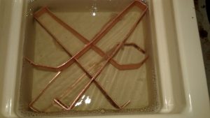
The custom-made replacement/conversion loops we make here at DuplexerRepair.com are painstakingly hand-made from high quality, 30-mil copper. They are measured and cut by hand, drilled, de-burred, shaped,
Custom-made replacement/conversion loops being ultrasonically cleaned prior to polishing and installation in the loop enclosures.
ultrasonically cleaned, and polished before installation in the loop enclosure. When we do the full loop assembly conversion job, we clearly mark the new designator on the underside of the flange, and typically label the outside of the enclosure as well with the conversion date and the new designation number. If we replaced the capacitors in the loop, we like to mark that on the outside as well, including the date the capacitor was replaced. Repeated failure of capacitors — especially in the same cavity position in a set — is a sign that something else in the repeater/transmitter system may be occurring which needs to be corrected.
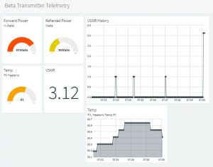
Several additions and modifications have been made to the development/beta version of this transmitter telemetry system over the
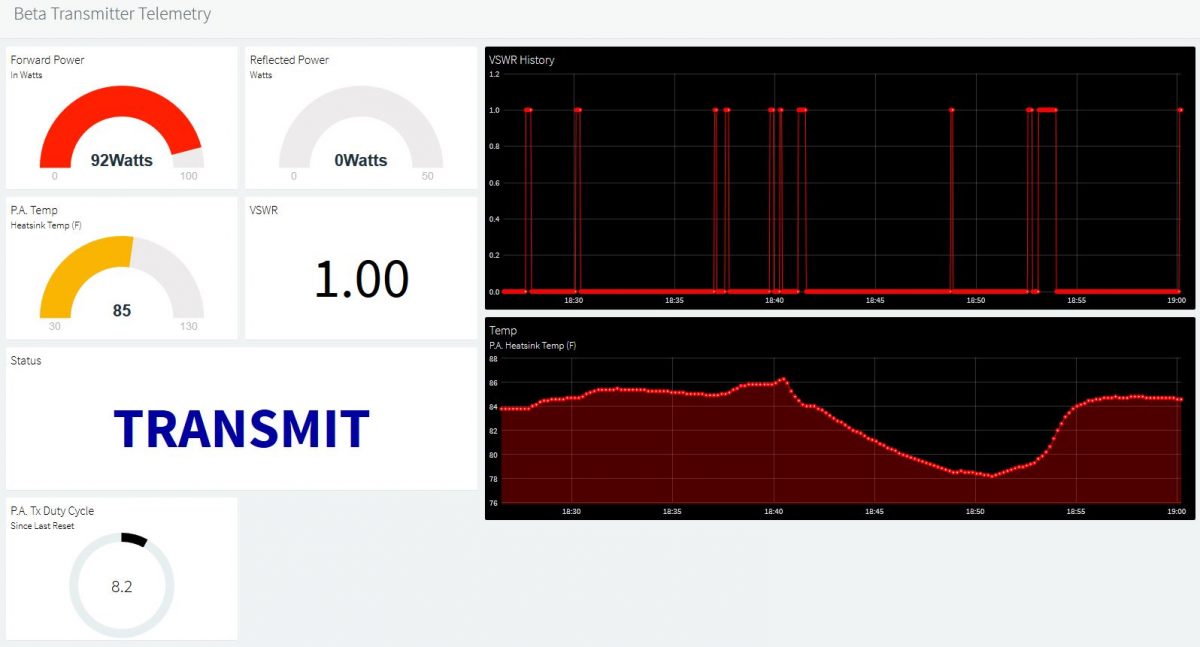
The latest look and feel of the online telemetry dashboard, developed as of the beta version 1.4 Arduino Sketch code.
past couple of days. Keyline status monitoring has been added to the circuitry and code (indicating whether the transmitter is in “STANDBY” or “TRANSMIT” mode) which can be seen in real time on the updated dashboard, which has a few added features, including up to 24 hour graphing of the P.A. heatsink temperature, and P.A. duty cycle percentage display. As I mentioned before, this is a “work in progress” and the imagination is about the only limit to what I can build into this telemetry system.
————————————————–
[Original post] Having gotten the Power & SWR Monitor Panel with LCD display to a state that it’s ready to operate permanently on one of the paging transmitters
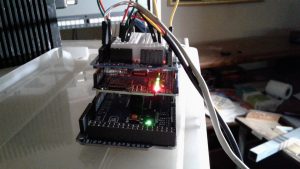
Arduino Mega 2560, topped with an Ethernet shield, along with a Prototyping board with breadboard for convenient modifications, additions, etc.
owned by a client, I’ve already begun developing the next generation of the project: an IoT based monitoring system which provides real-time monitoring of system performance.
This generation of the project utilizes an Ethernet shield running on an Arduino Mega development board. It also has the added feature of temperature monitoring. The thermal probe is strapped to the back of the P.A. heatsink assembly for now. I plan to test locating the thermal probe inside the P.A. final stage cavity, but it remains to be seen whether the high level of RF inside the cavity may interfere with the circuitry which is actually located inside the working end of the probe.
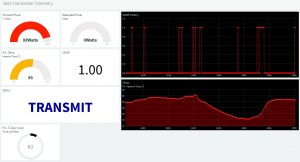
Screenshot of the online telemetry as it appeared during an intentionally created high SWR event (transmission line disconnected.) VSWR calculated as 3.12:1. (Note: the dashboard no longer looks exactly like this — see photo posted in 11/24/18 update above for the latest version.)
The system monitors and will remotely display forward RF power, reflected RF power, SWR/VSWR, and the heatsink temperature. I am considering adding monitoring of the “key” line. The purpose of doing that would be to be able to remotely determine whether a system malfunction (pages not being transmitted) was related to problems with the linking receiver system (which would result in no transmit “keying” of the other components in the system), keying with no or low P.A. output (most likely P.A. or exciter failure or malfunction), or high SWR (antenna or transmission line issues.) The latter two are already covered, but being able to narrow down a link receiver radio issue before even packing up for a service call could be very useful (one of those radios weighs about five pounds… if you’re familiar with Glenayre/Quintron equipment, then we don’t even need to talk about how much one of the Glenayre or Quintron power amplifiers weighs!)
Now, it’s time for coffee while I sit and ponder what cool things to do to this creation next. It is truly a work in progress.
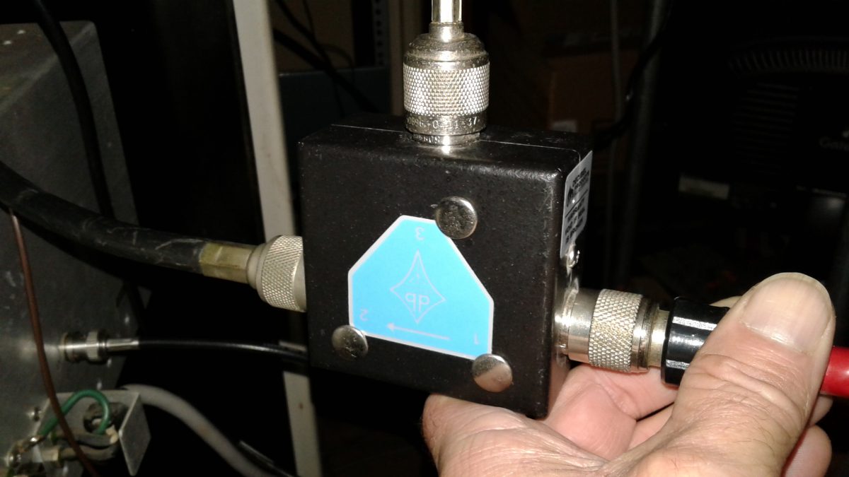
I often get asked “Do I really need to spend the money to purchase an RF isolator and have it tuned for installation on my repeater or transmitter? And, if so, why?” In this video, I demonstrate (and test) a db Products (Decibel Products) DB4613-1A isolator on a 100 Watt paging system, showing how the isolator protects the P.A. from high SWR (even full reflected power) in the event of broken, damaged, shorted, or disconnected feedline, damaged or iced-over antenna, etc. Just take five or six minutes to watch this video and you’ll fully see for yourself why an isolator is an excellent investment for your system. DuplexerRepair.com provides professional, precise tuning and testing of isolators, with quick turnaround and full testing — including a custom report showing the tuning and performance of your isolator when it’s finished.
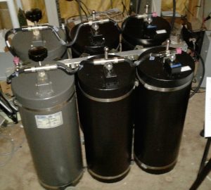
We’ve recently converted a couple of sets of Decibel Products (a/k/a/ dbProducts and dbSpectra) 4-Cavity 4060-WOC-C duplexers to 4062-WOC-B models. Translation:
4062-WOC-B Duplexer built by converting a new set of 4060-WOC-C cavities to “B” models, and overhauling and converting two additional “C” cavities from a failed set, resulting in a great working 6-cavity “B” model with over 100 dB of isolation in each branch.
we’ve converted 4-cavity sets which were built for operation at higher, public safety and commercial frequencies to 6-cavity sets which are optimized for operation in the 2-Meter Amateur Radio / ham frequency bands.
Doing so involves a fair amount of time and work, including total overhaul of each cavity, custom manufacturing of the correct length loops, capacitor replacements, and the building of a new frame for the expanded 6-cavity set, not to mention final tuning and performance testing.
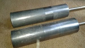
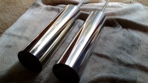
Tuning Plunger Removal, Inspection, and Polishing
After disassembly of the old cavities, one of the many steps in the overhaul and conversion process involves getting the tuning plungers back in good
Aged, oxidized tuning plungers BEFORE cleaning and polishing.The same two tuning plungers after careful cleaning and polishing.
shape. As can be seen in these photos showing the plungers before and after the application of some TLC, the difference is more than visible. So is the resulting performance and ability to be accurately tuned (and for that tuning to remain stable.)
Custom Copper Loop Fabrication and Loop Enclosure/Cavity Conversion
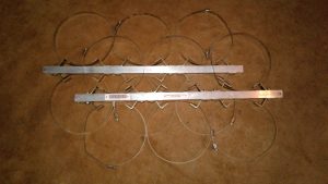
In order to obtain the best cavity SWR (lowest insertion loss) along with the maximum branch notching/isolation performance, the copper loops in one
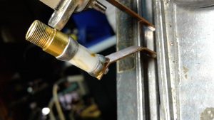
Original capacitor with signs of excessive heating, old flux residue which had not been cleaned off after soldering, etc. This capacitor had failed, causing the set to be taken out of service.New capacitor and custom made loop installed. The enclosure has been relabeled from the original “003” part number to its new, proper “005” designation.
branch of the duplexer assembly have to be replaced with loops of the correct length. At DuplexerRepair.com, we handcraft the replacement copper loops. We start with high quality, 30-mil copper and carefully cut, shape, drill, and polish the replacement loops.
During the installation of the new, replacement loops of proper dimensions for 2-Meter operation, we also replace the trimmer capacitors. This is actually a delicate process, as these capacitors do not tolerate excessive heat. It is quite common for us to discover signs of overheating from the combination of the original capacitor installation, soldering, and RF heating over time (mistuning, high SWR, and lightning will destroy these capacitors pretty easily.)
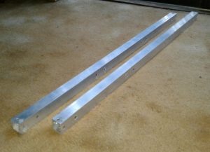
Frame and Mounting Rail Fabrication / Conversion
The original 4-cavity frame and mounting rails for assembling the cavities into a set have to be replaced in order to accommodate six cavities. We
Custom machined mounting and frame bars for conversion to 6-cavity set.New custom made rails with cavity braces and clamps installed.
custom machine these from square aluminum tubing.
Reassembly, Cable Harness Inspection and Service, and Final Testing
With all the components overhauled and reassembled using the new frame and mounting rails, each cable, Tee-connector, etc. is inspected and cleaned
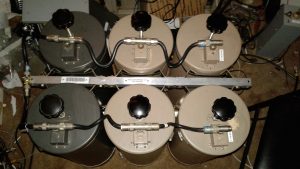
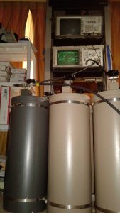
Another 6-cavity 4062-WOC-B set we recently converted, overhauled, and built, reassembled and ready for final tuning and testing.Duplexer assembly being put through final tuning and performance testing and verification. The client gets a complete report of the testing, including the network analyzer graphs showing proof of performance.
or replaced as necessary.
Each cavity is then individually performance tested, followed by connecting each branch as a set and testing it, and finally the entire harness is secured and the entire set undergoes its final tuning and performance testing.
The End Results
A complete conversion, expansion, and overhaul job such as the ones described here, commonly involves between 15 to 20 hours of labor, plus
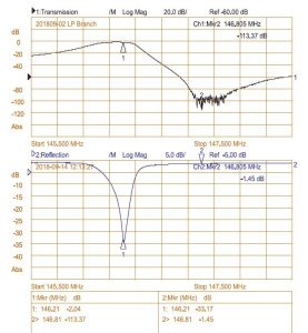
With 113.37 dB of isolation (factory spec is 100 dB or higher) with only 1.45 dB of IL (Insertion Loss (factory spec is 2.2 dB or less), this set is working considerably better than factory specifications. Well worth the investment of time, money, and energy.
materials. It’s not exactly cheap, but the results are worth it. What usually starts out as a 4-cavity 4060 “C” model (not built for factory spec operation in the 2-meter Amateur radio band, and often a set which has failed and been pulled from service) becomes a great working 4062 “B” model — as though it left the factory as a set intended to work to specs in the 2-Meter band. The 4-cavity 4060 models are rated at 80 dB or more of branch isolation; whereas the 4062 6-cavity sets are rated for 100 dB or higher isolation. At the typical 600 KHz “split” used in 2-Meter band, this extra isolation makes a world of difference, especially at transmitter power levels above 40 watts or so, and can be a game-changer when trying to get better performance out of certain repeaters, such as the Yaesu Fusion DR-1/DR-1X series, which tend to have lower receiver selectivity compared to most of the commercial grade repeaters with highly selective physical filtering on the front-end. Very often we deal with duplexers sent to the DuplexerRepair.com labs with complaints of “They worked great for years with our old Mastr II repeater running 40 Watts, but when we bought and installed a new Fusion repeater (or D-Star repeater, DMR machine, etc.) everything went to crap.”
We deal with such all the time. And we’re here to help. Call or contact us if you’re experiencing similar problems. We’ll be delighted to help you get things working the way they should. As they say, “A chain is only as strong as its weakest link.” Duplexers which aren’t up to the task will result in a poor or totally useless repeater setup. It doesn’t have to be that way. We’re here to remedy that.
Having accurately calibrated equipment here in the DuplexerRepair labs is a must, but sending instruments out to have them calibrated so that we know we’re calibrating and tuning your equipment accurately is very expensive. It also takes the equipment out of service if it has to be sent to an outside lab. Knowing that the ideal solution to keeping the equipment in service, accurately calibrated, and controlling costs would be to have an accurate in-house frequency standard, we decided to explore options such as calibrated rubidium oscillators, cesium driven units, etc.
Rubidium and cesium units have a few disadvantages. First is the cost. They can be very expensive, on the order of several $K for a new one. Second, they have to be re-calibrated periodically due to the natural aging of the oscillator devices. The ongoing cost and the uncertainty between calibrations makes them even less appealing. The solution we were looking for needed to be a combination of:
Accuracy
Reliability
Affordability
Availability
After much research, the decision was made to go with a GPS Disciplined Oscillator (GPSDO) system. Such a system, as the name implies, utilizes signals from the GPS satellites to precisely control a local oscillator. Each of the GPS satellites in operation are equipped with cesium and/or rubidium clocks and timing circuits. These are in turn all synchronized to the National Institute of Standards and Technology (NIST) cesium clock, which is considered the standard for time and oscillator frequency accuracy in the U.S. By knowing the maximum levels of uncertainty (error) of each device in this chain, it is possible to create a reference system for use in the lab which is traceable all the way back to the NIST. The maximum error in this chain is small — very, very small. We’re talking down to a fraction of a billionth of a second variability. When you convert that time error to a frequency error, it is equally small. It’s much smaller than the level of accuracy required for communications equipment and the manufacturer calibration standards for the equipment we use here in the lab to work on that equipment. The next question was whether to purchase a ready-built system or build it in-house. After much consideration, the decision was made to just put one together right here in the lab using readily available, affordable modules and devices, and design and build any additional components needed for the system.
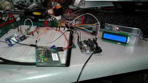
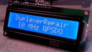
Left to right in this photo, are the GPS module and buffer board (sitting atop the breadboard which was used to initially design the buffer board circuitry), the Arduino Uno module, and the LCD display module, all interconnected and functioning. All of these will be assembled into a rack-mount unit.
Our GPSDO system, as seen in the photo as it was being assembled and tested here on one of the lab benches, consists of essentially four subassemblies, three of which are off-the-shelf items, and one module/board which was created right here in the lab:
Ublox Neo-M7M GPS Receiver module
Arduino Uno module
16×2 LCD Display module
Custom designed signal buffering/conditioning board
Once all of the off-the-shelf items were in hand, the task of designing and refining the special buffer board which takes the
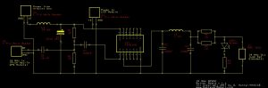
Buffer Board schematic.
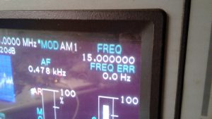
oscillator output from the GPS module (a square wave) and conditions and converts it to a usable sine wave at a very specific frequency took about a week (squeezing it in between other work.) This buffer board also provides impedance matching so that it can be connected to the instruments in the lab as a frequency standard, phase synchronization device, and calibration reference for radio equipment, frequency counters, and other instruments. Our final working prototype is not exactly the most aesthetically attractive looking thing in the world, but it sure does work well. How well? A good example can be seen in the following photograph showing that the IFR (running on the GPSDO system as a 10 MHz reference oscillator) indicates that WWV’s 15 MHz signal to be 15.000000 MHz with an error of 0.0 Hz.
The carrier frequency of WWV’s 15 MHz transmission out of Boulder, CO, as read by the IFR 1600 with our GPSDO connected as its frequency/oscillator reference.
Since we can only see one decimal place beyond the Hz digit in this example, the fact that the 1/10 of a Hz digit is rounding to the digit “0” means the value the IFR is coming up with must be in the range of -0.05 and +0.04 Hz, which equals a calculated maximum error of +/- 0.05 Hz. In the case of our 15 MHz frequency (15,000,000 Hz) that’s equivalent to an error of 0.00333 PPM (or 3.33 PPB, depending on which reference you prefer.) That is way better than the level of accuracy required for communications work. As an example, the FCC says that in land mobile radio equipment, the permissible carrier frequency error for a fixed transmitter operation in the range of 50-450 MHz is 5.0 PPM. Do a little math and you’ll see that our GPSDO has the IFR operating at roughly 1,500 times the level of accuracy required by the FCC rules. Sweet! Even sweeter is the fact that — unlike a rubidium frequency standard which has to be sent off for calibration once a year or so — our GPSDO is essentially updating its own calibration several times a second by constantly receiving the GPS signals and synchronizing itself. With an active gain GPS antenna attached, it rarely indicates being locked on less than 10 satellites simultaneously. It only takes four satellites to achieve a super-accurate “lock” but ours typically registers being locked on 11 and even 12 satellites. Did we mention that is with the antenna still inside the lab? Although it appears quite unnecessary, in the interest of maintaining the best lock and avoiding any potential interference to the GPS performance from equipment running here in the lab, we’re going to be installing an active, weatherproof, marine grade GPS antenna in an elevated position outside the lab. Another benefit of this GPSDO system is the fact it can achieve an accurate frequency lock in less than three seconds of power-up; whereas, rubidium standards employ temperature compensated ovens and typically have to be powered up for several hours for their oscillators to warm up before they stabilize and can be used as a reliable lab reference.
The icing on the cake in this recipe is the affordability of the project. Here’s a rough breakdown of the cost of creating this:
$15.30 — uBlox Neo-M7M GPS Module
$19.48 — Active GPS antenna and necessary adapters and cables
$5.45 — Arduino Uno (“knock-off”/compatible 3rd party clone)
$8.79 — 16×2 LCD Display with I2C interface module
>$10.00 — estimated cost of perf board, electronic components, etc. to build prototype “buffer board”
——————————————————
$59.02 — estimated final cost
That’s less than the one-way shipping cost of sending just the IFR analyzer off for calibration (and don’t even ask the actual cost of the calibration service — it’s astronomical.) With a hyper-accurate 0.00333 PPM frequency reference in-house, that’s exactly where the calibration work on our instruments will be done if/when needed.
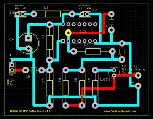
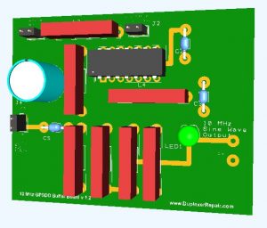
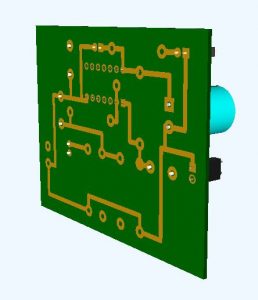
PCB layout design for the version 1.2 GPSDO Buffer Board.3D rendering of the v1.2 Buffer Board.3D rendering of the reverse side of the v1.2 Buffer Board.
A rework of the schematic and accompanying PCB layout have now been completed and we’ll soon be fabricating a nicely laid-out version 1.2 of the Buffer Board. Once we’ve fully assembled and tested that prototype board, we’re considering having several of the boards manufactured so that others who are interested in putting together a similar system can simply purchase one of our buffer boards and the parts to populate it (which we might offer in a kit form.) Estimated time to solder all the components is roughly 30 minutes to an hour, depending on how well versed you are with a soldering iron.) There might be a version 2.0 board in the works as well — using SMD components to further reduce the cost, board size, power consumption, and to reduce the amount of RF emission.
Okay, so your old Mastr II was pumping out 50, 75, maybe even 100 Watts with no problem using your trusty old duplexers, but then you installed a shiny new Yaesu Fusion and the proverbial “stuff” hit the fan. Desense galore. Poor sensitivity. User complaints about not being able to carry on a QSO like before — all other factors being equal. You’ve even tried backing the Fusion’s transmit power down to half or less of what you’d been running the old Mastr II’s PA at (or maybe it’s a Motorola) but you still feel as though you’re chasing your tail. I’ve received countless calls, messages, emails, etc. asking for help and advice with this problem. I have known since my very first encounter with a Fusion repeater essentially what the problem was — and various solutions — but today I actually went to the effort to do in-depth technical testing and put some real numbers with it. In all honesty, it’s a bit worse than I had estimated.
The problem is one of “selectivity” — not to be confused with “sensitivity.” Two totally different beasts. My testing does show the sensitivity of the Yausu Fusion to be pretty close to that of the Mastr II and other commercial grade repeater equipment. Where it can’t compare is in selectivity — the ability of the receiver to effectively hear what it’s supposed to while suppressing and not getting swamped by other signals, including (especially) its own transmit frequency. Because the Fusion is much less selective (just how much so you’ll see shortly) you can’t get the same performance out of the Fusion that you were accustomed to with a Mastr II, Motorola, or other truly commercial grade repeater if you try to use the same duplexers. High RF environments such as broadcast transmitter sites or sites with multiple repeaters in operation also become a problem at times with the Fusion; whereas, the old Mastr II and other systems seemed to work okay.
There are a combination of factors which make the receiver in one repeater more or less selective than others. I’ll spare you all the discussions of “Q” and how amplifiers, transistors, etc. actually lose gain at the desired receiver frequency when there’s a lot of RF on frequencies close to it (such as just 600 KHz or so away — typical of ham repeater in the 2-Meter band), but we can’t avoid mentioning it altogether. True, your duplexers help reduce much of the unwanted signals, but they never block 100% of it. The less selective the repeater’s receiver is, the more isolation between the receive and transmit frequencies is needed in the duplexers. By contrast, higher selectivity in the receiver means you can get away with lower “dB” isolation in the duplexers. For example, a Mastr II might work fine at 50 Watts on a high quality set of 4-cavity duplexers, or at 100 Watts on a 6-Cavity set, but the Fusion often takes repeater owners on a not-so-fun journey into desense land at 50 Watts (sometimes 25 Watts) on the same 4-cavity set that the Mastr II had played nicely with in the past. My testing this morning shows how much so.
In order to conduct side-by-side, “apples to apples” testing for comparison purposes, here’s how I set everything up and conducted the tests.
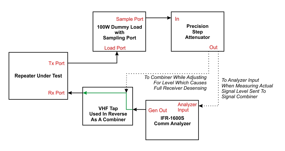
Lab testing setup used for measuring comparative selectivity/desense levels of the Yaesu Fusion DR-1 repeater and a G.E. Mastr II repeater. Tests conducted in VHF/2-Meter band only.
With the setup above, I sent a signal from the IFR-1600S to a combiner, the output of which was in turn routed to the receiver port of the repeater being tested. With the repeater activated, the transmitter output was sent to a 100 Watt dummy load with a reduced level sampling port. The output from that sampling port was then fed to a precision attenuator capable of 1-101 dB attenuation in 1 dB steps, the output of which was combined with the IFR’s output at the second input port of the combiner. This setup allowed me to combine a precisely adjustable amount of the transmitter’s output signal with the desired receive signal. By slowly decreasing the amount of attenuation of the transmit signal allowed into the combiner, I was able to determine how much RF power getting back into the repeater’s receiver would cause desensing. I kept adjusting until the level of the transmit signal going back into the combiner was high enough to cause total desensing of the receiver, meaning that the receiver was unable to discern enough receive signal to even do “cyclic” type key/unkey/key/unkey repeated desensing. The levels I created and measured resulted in total loss of useable reception in the receiver, effectively deafening and shutting down the repeater’s functionality altogether.
It is important to note that this testing does not address the levels at which “white noise” from the transmitter starts causing voice/modulation quality degradation in the repeater’s output. “White noise” and transmitted voice/modulation quality actually start occurring at much lower levels of unwanted transmit RF getting back into the receiver. Such noise gets progressively worse as the level of unwanted signal creeping back into the receiver increases, until it reaches the total desense level. Thus, the amounts of transmit/receive isolation needed (discussed a bit later in this article) in order to have clear, enjoyable QSO’s is actually considerably higher than the levels of rejection/isolation necessary just to avoid total desensing. Don’t use the isolation numbers shown in a bit to be the duplexer performance level you need for your repeater. Rather, the levels discussed in this article allow side-by-side comparison of the selectivity — or ability of each repeater’s receiver to block troublesome, unwanted signals and actually “pick out” and properly demodulate the desired signal.
For testing purposes, I used the following signals:
Rx signal for the repeater: 147.660 MHz, modulated with a 1 KHz audible sine wave tone modulated at 3.0 KHz deviation, and a 123.0 Hz CTCSS tone modulated at a 0.6 KHz level for repeater PL tone operation. Signal level from IFR-1600S set to 0.224 uV for testing of both repeaters.
Tx signal from repeater: 147.060 MHz with no tone generation being added by the repeater.
I chose these particular frequencies and tones for a simple reason: I had recently done a Mastr II repeater conversion for a local amateur radio club using that frequency pair and tones but it was still here in the lab, so a well functioning, properly aligned Mastr II set up as such was readily available. The Yaesu Fusion — being fully programmable and agile — was thus easy to set for identical frequencies and CTCSS operation.
Once I fired up each of the repeaters and had adjusted the level of the transmit signal being intentionally looped back into the receiver so that total desense occurred, I simply disconnected the feedback line from the combiner, which allowed the repeater to start repeating again. The level of the transmit signal coming from the test port of the dummy load and going into the precision attenuator had been measured just before conducting each desense level test. By calculating the resulting level after attenuation and factoring back in the amount of loss presented by the combiner, I was able to calculate the power level (calculated in uW (microwatts) in this instance) and record it. After putting both repeaters through this same test, I had the desired numbers at hand. I already knew that the differences between the Mastr II and Fusion would be noticeable, but they turned out to be a bit more so than I had suspected.
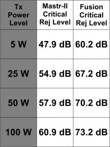
The Fusion repeater would totally desense with unwanted transmitter signal power of 4.77 uW. Contrast that to 80.8 uW that it took for the G.E Mastr II to reach total desense and a lot of things start becoming clearer. This table lists what I’ll refer to as the “Critical Rejection Level” — the amount of transmitter/receiver isolation necessary to prevent total desensing of the receiver for each
Calculated Critical Rejection Levels for comparing the selectivity and desense avoidance capabilities of the Yaesu Fusion DR-1 and the G.E. Mastr II operating in the VHF/2-Meter band.
repeater. The table shows this estimated value calculated for operating each repeater at four power levels: 5, 25, 50, and 100 Watts. Please keep in mind, as mentioned before, that these are not intended to be absolute values to use for specifying duplexer parameters, etc. They are, however, numbers useful for comparison of the selectivity and desense avoidance capabilities of the Fusion and Mastr II. In my overall experience, the amount of transmitter/receiver isolation necessary to actually have relatively white noise-free, clear QSO’s in a repeater are generally 30-40 dB or so greater than what I refer to as the Critical Rejection Level. Shooting the middle and adding 35 dB to the numbers in this table yields numbers very comparable to the actual values of duplexer Tx/Rx isolation I’ve found necessary in real-world practice. I have found that the G.E. Mastr II VHF repeater will typically operate well in a relatively RF-clean environment with 80 dB or greater Tx/Rx isolation up to around 40 Watts, and do well up to 100-125 Watts with at least 100 dB of isolation. By contrast, the Yaesu Fusion is best operated with at least 80 dB of duplexer Tx/Rx isolation at 25 Watts or less, and definitely needs 100 dB or better in order to operate at its 50 Watt transmitter power level or with an outboard power amplifier running between 50 and 100 Watts (again, in a relatively CLEAN RF environment.) Also, these numbers relate only to transmitter/receiver isolation. Operating a repeater in a high-RF environment such as a commercial/broadcast transmitter site will create the need for specialized filtering (such as pre-filters), increased duplexer isolation rating needs, and frequently create intermodulation problems that call for lots of creativity and sometimes end up being impractical to try to overcome. I also have not done extensive testing to see whether or not the Fusion’s transmitter final/PA output is as good as the Mastr II in terms of any harmonics, spurious artifact, etc. in its “Fixed Analog FM” output mode. I suspect that it isn’t, but that’s research for yet another day. For now, suffice it to say that if it’s not, then things get even worse, but for the moment let’s at least imagine that the Fusion and the Mastr II have exactly the same output signal quality.
I am considering repeating these tests using the Fusion in UHF/70CM band and a Mastr II running at the same frequency/band. Almost all complaints I’ve heard regarding the Fusion having desense problems have been in the 2-Meter band, so that was my focus for today’s testing and documentation purposes.
I hope that this information sheds some light on why Fusion repeaters installed as replacements for Mastr II repeaters (and other commercial grade repeaters, such as Motorola equipment) so often create frustration and sleepless nights for so many repeater operators. My hat is off to the folks at Yaesu for creating some exciting, feature-rich repeaters in a price range that put them within the reach of many repeater owners who thought they’d never own a brand-spanking new repeater. Anyone considering purchasing a Fusion just needs to keep in mind that Fusion repeaters are ultimately ham/consumer level equipment and understand that they will not perform as well for analog communications as will a Mastr II or other commercial/professional grade repeater. Installing a Fusion using the same antenna, duplexers, connectors, and other hardware that was previously used with a properly working and aligned commercial grade repeater can and will quickly lead to great frustration unless you’re prepared to make a combination of changes and/or concessions.
This post could appropriately be subtitled “The Costs of Doing Good RF Business.” I’m a fan of Decibel Products duplexers because they do an excellent job in repeater applications. But like any piece of hardware, they are not immune to damage or failures. Many of Decibel Products’ duplexers (most notably the DB4060 and DB4062 VHF models) utilize precision trimmer capacitors which are the sort of component you love to hate.
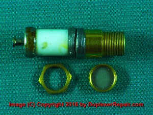
Capacitor shown with retaining nut and protective cap. This capacitor required replacement due to failure. Discoloration can be seen on the white ceramic portion which resulted from excessive heat.
On the plus side, the capacitors (commonly referred to as “Johanson capacitors, after the company which manufactured the bulk of the caps used) are known for the ability to be very precisely tuned, largely due to the fact that it takes around 20 turns of the capacitor’s adjusting screw to go from one end of its capacitance range to the other. Compare this to many open plate type capacitors which go through their full capacitance range in only 1/2 turn and it’s obvious that very accurate and precise tuning is much easier using the Johanson type capacitor; however, utilizing them in a duplexer cavity also makes the cavity a bit more prone to fail under certain conditions. That’s the trade-off involved.
The very design elements which make the Johanson capacitors so great also make them much more fragile and more easily damaged. First of all, they are very small. The diameter of the outer ceramic cylinder of these capacitors is only 0.244” (6.20 mm to be more precise.) The component is hermetically sealed from the outside environment, which is good, because moisture and dust are enemies to such devices. At the same time, the very small enclosure size means that any heat in the device pretty much STAYS in the device until it dissipates through by conductive and convective methods — not always a fast process.
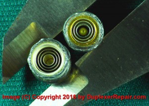
Capacitor disassembled to show the concentric, cylindrical “plates,” which mesh with free space between them, thus forming a capacitor.
The actual capacitance creating part of these capacitors is a combination of concentric cylinders. One set of concentric cylinders is permanent attached to a stationary end inside the ceramic cylinder. A second set of cylinders is attached to the adjusting/tuning screw which has very, very fine pitched threads, giving the capacitor highly precise tuning ability because it takes so many turns to adjust it from one end of its range to the opposite end. As the screw is adjusted, this second set of metal cylinders moves in and out of the stationary set. If you’re familiar with electronics theory, you’ll recall that the two ways of varying the value of a capacitor (without altering the material used) is to either increase/decrease the size of the plates, or alter the spacing between the plates. A sort of combination of both variables has been accomplished in open-plate capacitors for ages by physically rotating one set of plates in and out of a second set in a horizontal fashion. This is the type of variable capacitor we see commonly used in everything from tiny transistor radios to the large open-plate variable capacitors used in high wattage antenna tuners/matchers. The difference in the Johanson capacitor’s operation is that they accomplish the same thing by changing how deeply the sets of concentric metal cylinders are meshed. They simply move in or out in a linear fashion.
The largest of the metal capacitor plate cylinders measures approximately 0.193″ (4.90 mm) outside diameter. Keep in mind that’s the LARGEST of the cylinders, which get increasing smaller in size, and there are seven total cylinders between the two sets. The smallest of the capacitive plate cylinders is approximately 0.063″ (1.60 mm) outside diameter. Metal objects this small can’t handle much heat, for starters. As those of us in the electronics and communications world all know, heat is not our friend. At the least, heat causes metals to expand. Given the miniscule size of these cylindrical capacitor plates, it wouldn’t take much heat to totally alter their size — thus the effective spacing between them — thereby changing the capacitance. These capacitors are used in the duplexer cavities to tune the rejection notch; therefore, if the capacitance changes, the notch tuning changes. If the notch tuning changes, the pass/reject performance of the cavity changes. In short, excessive heat buildup in the capacitor will cause the cavity and the duplexer set to fall below designed performance specifications. This obviously is not what we want happening.
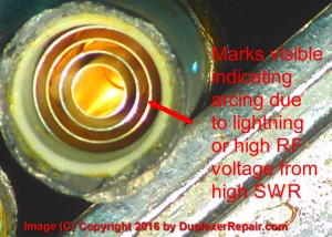
Pitting and burn marks were visible on microscopic inspection of the cylindrical plates inside this failed capacitor.
What would cause excessive heat buildup? A number of factors contribute to heat in the capacitors. First, RF energy by its very nature produces some amount of heat. That’s unavoidable. Many of the repeaters built or serviced by DuplexerRepair.com operate upwards of 100-125 Watts maximum. The higher the power from the repeater’s power amplifier, the more heat is generated in the cabling, duplexer cavities, and most importantly in the capacitors and other “loop” components. While RF energy that’s flowing through the devices is just part of the process, there are other causes which aren’t part of normal repeater operation which can be downright catastrophic, especially to these fragile capacitors we’re discussing.
High SWR in the antenna and feedline system can cause abnormal amounts of RF energy that’s supposed to be leaving the antenna in the form of electromagnetic waves to actually reflect back down the feedline to the duplexers. Since these capacitors are intended to help block the unwanted frequency from getting through by essentially creating a short-circuit to ground (the cavity cylinder itself is grounded) any increase in RF through the capacitor means increased heat. If the heat becomes great enough, the tiny capacitor cylinders themselves can expand to the point that they make physical contact between cylinders, essentially creating an RF short-circuit to ALL RF energy (meaning the frequency that’s supposed to be getting blocked along with everything else.) This short-circuit only leads to more and more heat, and it is commonly a cause of power amplifier/transmitter damage and failures as well. The end result is a catastrophic failure. If your antenna is mistuned or has problems leading to increased SWR, your duplexers are more likely to fail because of damage to these capacitors. Likewise, feedline problems such as physical damage (or even poor grade cabling/feedline) can cause high SWR and eventual failure. Lastly, mistuning of a cavity — even relatively slight — means needlessly increased RF energy is hitting places and components where you don’t want it to. Tick, tock… it’s just a matter of time until trouble occurs.
There’s also our other enemy in the radio world: lightning. Let’s face it, there’s not much need for technical explanation of the effects of lightning here, because we know it’s just downright destructive to communications equipment, and if it directly strikes an antenna (or even in close proximity) even the highest quality lightning protection devices can only do so much. If a hundred or so watts of misdirected energy can damage one of these capacitors, just imagine what a few megawatts from a lightning strike will do in terms of destructive effects. Enough said about that.
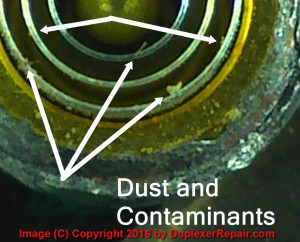
Micron-sized dust particles and/or moisture incursion into these caps will cause them to fail prematurely.
Dust particles and contaminants are theoretically kept out of these capacitors by sealing the plate cylinders inside the capacitor’s housing. The key word here is “theoretically.” Nothing is perfect. It only takes a few micron-sized particles of moisture or dust getting inside one of these capacitors to create a failure scenario. Moisture causes corrosion. Corrosion on the capacitive cylinders not only alters the capacitance but also creates potential conduction paths for electrical current which lead to RF short circuits. Dust particles similarly create unwanted conduction paths. Bottom line: we want to minimize any risk of contamination by moisture, dust, or other contaminant as much as
A Johanson-type precision trimmer capacitor properly dressed for work, with its cap in place.
possible. They aren’t healthy for radio equipment, duplexer cavities, or these capacitors in particular. These capacitors come with protective screw-on sealing caps. They should be kept on the capacitors and fairly firmly tightened at all times, the only exception being while tuning is being performed on the duplexer assembly. Otherwise, moisture and micron sized particles of dust, etc. can and will eventually make their way between the tiny threads and into the capacitor, causing an eventual failure. Likewise, although it should not need to be pointed out: proper control of the ambient environment where the duplexers are installed is worth all the effort you put into it.
If this adjusting screw feels too easy or too difficult to turn, replacement of the capacitor is most likely in order.
Something to watch for (or perhaps we should say “feel for”) if you’re tuning a set of duplexers which use these caps: very loose or tight feeling threads when turning the adjustment screw/slug. The screw should offer some/moderate resistance to being rotated for tuning; however, if it seems to spin pretty freely or feels as though it takes a lot of torque to turn it, the capacitor needs to be replaced. A loose turning adjustment screw usually means the capacitor is cracked (we’ve seen them broken completely into two halves, totally separated physically.) A tuning screw that feels excessively bound/tight typically means the capacitor has significant heat/lightning damage. In either case, you’ll only prolong the inevitable and end up “chasing your tail” trying to make the duplexers work properly and stay properly tuned and functioning. More often than not, Decibel Products duplexers we see in use by Amateur Radio folks are surplus/repurposed sets which had been used in commercial or public safety communications prior to being pulled out of service, eventually ending up in the hands of ham radio folks. We often suspect that the reason they were pulled from prior commercial/public safety use was due to… wait for it… failing capacitors which led to a two-way shop making the recommendation to just replace the whole set with new ones due to time constraints, and possibly because the radio shop can usually make more money selling a new set than they can by repairing the failed set. Plus, they often have to install another set immediately in order to get the system back in operation, so instead of the system being down twice it often makes more sense in those circles to just install new ones immediately. All that said, there’s probably a reason some ham got hold of the things for considerably less than the going price for new ones, and that reason is often undisclosed, unknown, and undetectable until attempts are made to actually put them to use in a repeater system. For those who have never done in-depth duplexer work, it’s worth mentioning that duplexers can often seem to work great when you’re testing and tuning them at power levels down in milliwatt/microvolt range but prove to be total garbage when you hit them with the sort of power levels coming out of a repeater’s transmitter. Experienced duplexer repair techs are better versed in things to look for which could spell trouble for duplexers in the real radio world.
There is another issue which can contribute to failure of these capacitors which should be pointed out: improper installation of the capacitors in the duplexer cavities. The capacitors most commonly used in the design of Decibel Products duplexers are attached to the cavity loop assembly by means of a stud/pin on the end of the capacitor which is soldered to the copper resonating loop. The opposing end is attached to the loop enclosure by means of a retaining nut. Because they are very easily damaged by heat, it’s extremely critical that the temperature and soldering time be precisely controlled. Not enough heat when soldering the capacitor in place will result in a poor solder connection (cold solder joint) which will have added resistance (heat buildup from RF current) or can open entirely, causing the cavity to fail. Too much heat during soldering will either destroy the capacitor immediately (and these things are not cheap) or do damage which will shorten the life of the capacitor tremendously. Proper installation of the retaining nut on the end of the capacitor which protrudes through the loop enclosure is also important. Too tight and the capacitor can be deformed and damaged. Too loose and the contact (conduction path) can be poor, plus the entire capacitor assembly may try to spin during adjusting, which can in turn break the capacitor assembly (if the solder joint at the other end is nice and strong) or torque the loop, resulting in deformation, pass frequency shifting, and a loop which might try to slowly move back into its proper shape (usually well after you’ve reinstalled the duplexers and left the repeater site) causing everything to go haywire — which Mr. Murphy delights in seeing happen at the most inopportune times. Decibel Products typically painted the loop enclosures AFTER installing the components including these capacitors. Some people complain about that making it more difficult to remove that tiny, ultra-fine threaded retaining nut. Don’t be a hater: by doing so they actually reduced the chances of the nut working loose and allowing things to move around which should be doing so. Kudos to Decibel for that decision. It’s not uncommon for the retaining nuts to bend, break, and generally become unrecognizable (not to mention unusable) when they have to be removed. That’s okay, because we only remove them to repair a loop enclosure (or modify it for operation at a different frequency range than it was originally manufactured for by fabricating replacement loops of the proper length for the desired frequency range.) If we break the nut, we’ll replace it, and it’s not uncommon for the entire capacitor to already be in need of replacement during the conversion. If we see signs of heat damage (such as discoloration on the ceramic enclosure) the capacitor will be replaced. At DuplexerRepair.com we are extremely careful and diligent when inspecting and installing these capacitors because we want you to get the longest possible life and best performance out of any equipment we repair or recondition. This in turn helps to minimize the risk of damage/failure of the other equipment in your communications system, such as your receivers, exciters, and power amplifiers.
By now you probably know more than you ever imagined you would (or wanted to) about the precision capacitors used in Decibel Products duplexer cavities. We just thought you deserved to be well informed of the pros, cons, and factors you should take into consideration regarding certain Decibel Products duplexers because of the capacitors used. We do highly recommend these duplexers because their design is excellent, their performance is fantastic, and the lifespan of Decibel Products duplexers between repairs/overhauls is wonderful, provided they — and the rest of your communications system — are installed and maintained properly. While we can’t control when and where lightning strikes will occur and cause damage to equipment, we can reduce the chances of system failures through proper attention to the details we do have some control over.
If you are the owner of a set of these Decibel Products duplexers and you need tuning, repair, conversion, or complete overhaul/refurbishing of a set, get in touch with us by calling (334) 787-9005 or by emailing service@duplexerrepair.com. We’ll have them in proper working order and back to you as quickly as possible (usually within 2-3 days, although sometimes it takes a bit longer, especially if parts/cables have to be fabricated or special-ordered.)

 Having accurately calibrated equipment here in the DuplexerRepair labs is a must, but sending instruments out to have them calibrated so that we know we’re calibrating and tuning your equipment accurately is very expensive. It also takes the equipment out of service if it has to be sent to an outside lab. Knowing that the ideal solution to keeping the equipment in service, accurately calibrated, and controlling costs would be to have an accurate in-house frequency standard, we decided to explore options such as calibrated rubidium oscillators, cesium driven units, etc.