At DuplexerRepair.com, we convert a lot of the Decibel Products / dbSpectra DB4062 VHF from higher frequency VHF models (“-C” model designator, 154-174 MHz range) to 2-Meter Ham / Amateur Radio operating range (“-B” model designator, 143-156 MHz range.)
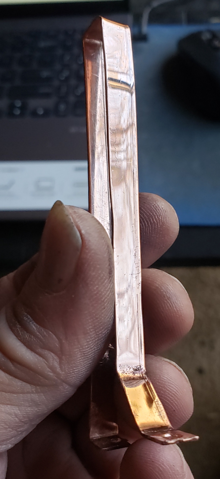
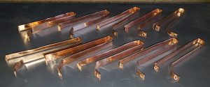
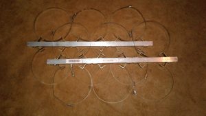
A finished, hand crafted “-B” loop, ready for installation in a loop assembly for conversion to Ham/Amateur Radio operating range.
Conversion to the “-B” model requires replacing half of the loops (2 loops in a DB4060 set, and three loops in a DB4062 set) with loops of the proper length. The required conversion loops are hand-made from stock, 30-mil copper right here in the labs of DuplexerRepair.
Starting with the copper stock, the copper is cut to proper size, then meticulously cleaned and polished. Then, the copper strips have to be marked, drilled, and properly shaped.
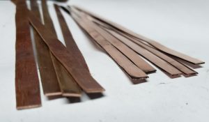
30-mil copper cut to the proper length and width for turning into -B conversion loops.
We just thought you might like to see some photos of how they look when they’re finished and ready to go into loop assemblies. What you are seeing in these photos is a batch which was just finished this morning in order to fill a couple of pending orders/jobs.
The latest batch of hand-crafted loops, ready for use.
This is a time and labor intensive process, but it’s worth it in the end, resulting in the duplexers actually performing to (usually better than) factory specifications for the -B model.
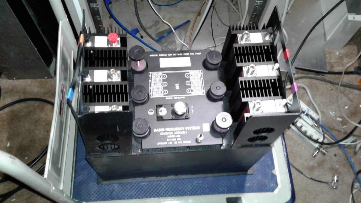
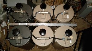
At DuplexerRepair.com, all tuning and service/repair jobs are taken seriously, but now and then an especially interesting item rolls into the lab for service. In this instance it was an RFS Corporation model WIJD862-05SSP 6-Channel, 800 MHz combiner. After retuning for a
change of frequencies/channel for the client, this 83 pound beast is nicely outperforming the factory specifications. It’s a rather impressive piece of communications hardware, although I have found RFS equipment to perform well in every instance.
Even after taking a good lick, it performs as expected — and better
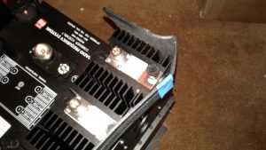
This one actually survived an apparent drop or impact to one corner of the box during shipment which had to be a pretty good “lick,” because it totally
The isolator mounting flange/handle showed evidence of a pretty good drop or hit during shipping, but the performance is still excellent.
bent one of the heavy gauge metal isolator mounting flanges (which doubles as a lifting handle.) Even after taking this hit, the combiner is performing great — better than factory specifications, in fact.
If you’d like to see for yourself just how well this thing performs, just click on this link to view the performance report which includes network analyzer graphs and photos of the unit and the mechanical damage which occurred during shipping.
Tuning one of these takes considerably longer than even a multi-cavity duplexer assembly, and it’s much more involved. But it’s actually a blast to do and it sure feels nice when you finish the work and see just how great it performs. Only thing is: after you move this heavy thing around it’s a bit tempting to add a line item to the client’s invoice — the cost of a trip to a chiropractor or a masseuse.
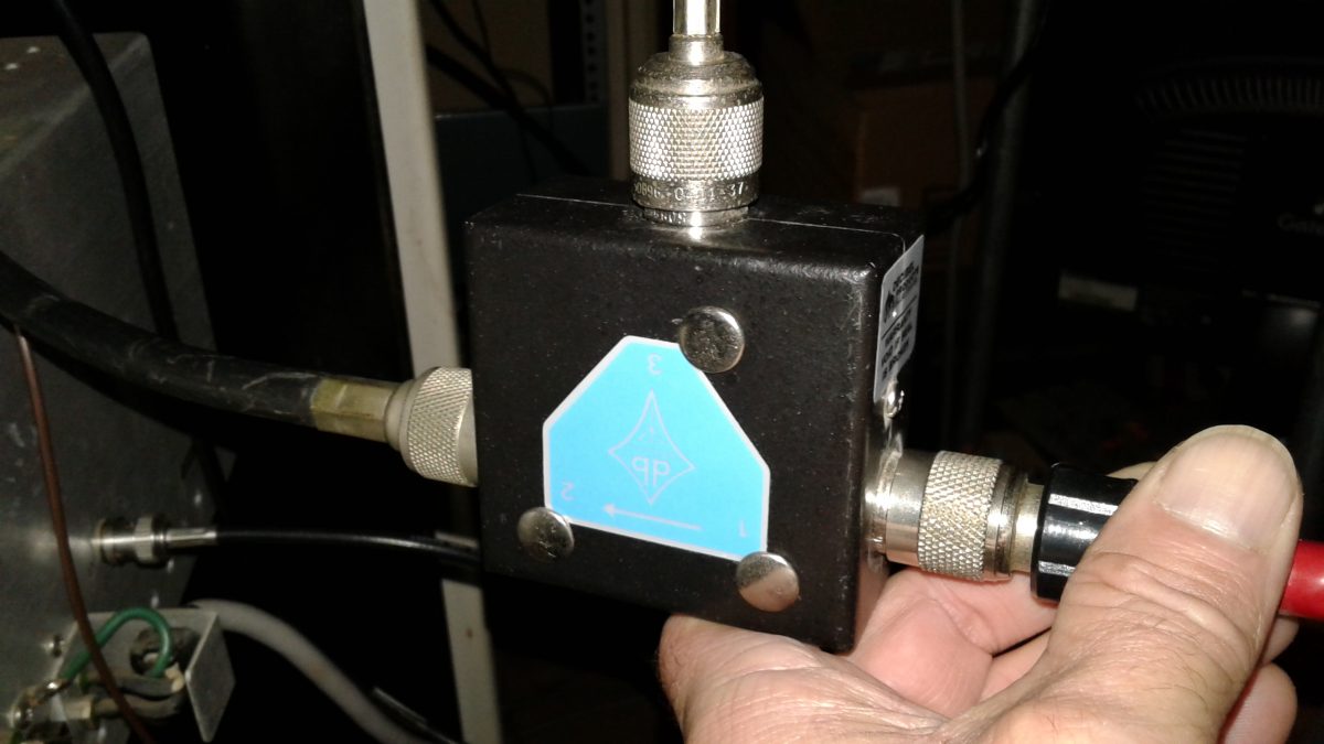
I often get asked “Do I really need to spend the money to purchase an RF isolator and have it tuned for installation on my repeater or transmitter? And, if so, why?” In this video, I demonstrate (and test) a db Products (Decibel Products) DB4613-1A isolator on a 100 Watt paging system, showing how the isolator protects the P.A. from high SWR (even full reflected power) in the event of broken, damaged, shorted, or disconnected feedline, damaged or iced-over antenna, etc. Just take five or six minutes to watch this video and you’ll fully see for yourself why an isolator is an excellent investment for your system. DuplexerRepair.com provides professional, precise tuning and testing of isolators, with quick turnaround and full testing — including a custom report showing the tuning and performance of your isolator when it’s finished.
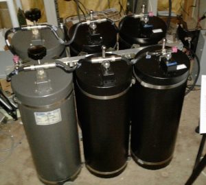
We’ve recently converted a couple of sets of Decibel Products (a/k/a/ dbProducts and dbSpectra) 4-Cavity 4060-WOC-C duplexers to 4062-WOC-B models. Translation:
4062-WOC-B Duplexer built by converting a new set of 4060-WOC-C cavities to “B” models, and overhauling and converting two additional “C” cavities from a failed set, resulting in a great working 6-cavity “B” model with over 100 dB of isolation in each branch.
we’ve converted 4-cavity sets which were built for operation at higher, public safety and commercial frequencies to 6-cavity sets which are optimized for operation in the 2-Meter Amateur Radio / ham frequency bands.
Doing so involves a fair amount of time and work, including total overhaul of each cavity, custom manufacturing of the correct length loops, capacitor replacements, and the building of a new frame for the expanded 6-cavity set, not to mention final tuning and performance testing.
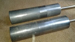
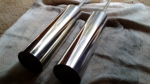
Tuning Plunger Removal, Inspection, and Polishing
After disassembly of the old cavities, one of the many steps in the overhaul and conversion process involves getting the tuning plungers back in good
Aged, oxidized tuning plungers BEFORE cleaning and polishing.The same two tuning plungers after careful cleaning and polishing.
shape. As can be seen in these photos showing the plungers before and after the application of some TLC, the difference is more than visible. So is the resulting performance and ability to be accurately tuned (and for that tuning to remain stable.)
Custom Copper Loop Fabrication and Loop Enclosure/Cavity Conversion
In order to obtain the best cavity SWR (lowest insertion loss) along with the maximum branch notching/isolation performance, the copper loops in one
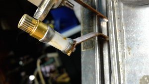
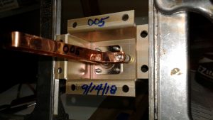
Original capacitor with signs of excessive heating, old flux residue which had not been cleaned off after soldering, etc. This capacitor had failed, causing the set to be taken out of service.New capacitor and custom made loop installed. The enclosure has been relabeled from the original “003” part number to its new, proper “005” designation.
branch of the duplexer assembly have to be replaced with loops of the correct length. At DuplexerRepair.com, we handcraft the replacement copper loops. We start with high quality, 30-mil copper and carefully cut, shape, drill, and polish the replacement loops.
During the installation of the new, replacement loops of proper dimensions for 2-Meter operation, we also replace the trimmer capacitors. This is actually a delicate process, as these capacitors do not tolerate excessive heat. It is quite common for us to discover signs of overheating from the combination of the original capacitor installation, soldering, and RF heating over time (mistuning, high SWR, and lightning will destroy these capacitors pretty easily.)
Frame and Mounting Rail Fabrication / Conversion
The original 4-cavity frame and mounting rails for assembling the cavities into a set have to be replaced in order to accommodate six cavities. We
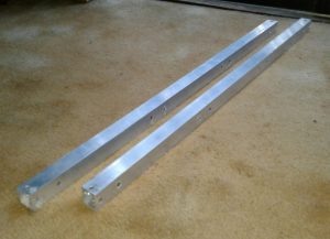
Custom machined mounting and frame bars for conversion to 6-cavity set.New custom made rails with cavity braces and clamps installed.
custom machine these from square aluminum tubing.
Reassembly, Cable Harness Inspection and Service, and Final Testing
With all the components overhauled and reassembled using the new frame and mounting rails, each cable, Tee-connector, etc. is inspected and cleaned
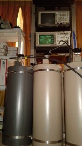
Another 6-cavity 4062-WOC-B set we recently converted, overhauled, and built, reassembled and ready for final tuning and testing.Duplexer assembly being put through final tuning and performance testing and verification. The client gets a complete report of the testing, including the network analyzer graphs showing proof of performance.
or replaced as necessary.
Each cavity is then individually performance tested, followed by connecting each branch as a set and testing it, and finally the entire harness is secured and the entire set undergoes its final tuning and performance testing.
The End Results
A complete conversion, expansion, and overhaul job such as the ones described here, commonly involves between 15 to 20 hours of labor, plus
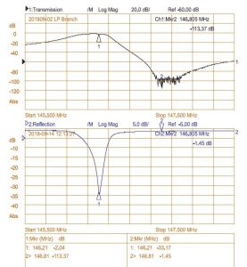
With 113.37 dB of isolation (factory spec is 100 dB or higher) with only 1.45 dB of IL (Insertion Loss (factory spec is 2.2 dB or less), this set is working considerably better than factory specifications. Well worth the investment of time, money, and energy.
materials. It’s not exactly cheap, but the results are worth it. What usually starts out as a 4-cavity 4060 “C” model (not built for factory spec operation in the 2-meter Amateur radio band, and often a set which has failed and been pulled from service) becomes a great working 4062 “B” model — as though it left the factory as a set intended to work to specs in the 2-Meter band. The 4-cavity 4060 models are rated at 80 dB or more of branch isolation; whereas the 4062 6-cavity sets are rated for 100 dB or higher isolation. At the typical 600 KHz “split” used in 2-Meter band, this extra isolation makes a world of difference, especially at transmitter power levels above 40 watts or so, and can be a game-changer when trying to get better performance out of certain repeaters, such as the Yaesu Fusion DR-1/DR-1X series, which tend to have lower receiver selectivity compared to most of the commercial grade repeaters with highly selective physical filtering on the front-end. Very often we deal with duplexers sent to the DuplexerRepair.com labs with complaints of “They worked great for years with our old Mastr II repeater running 40 Watts, but when we bought and installed a new Fusion repeater (or D-Star repeater, DMR machine, etc.) everything went to crap.”
We deal with such all the time. And we’re here to help. Call or contact us if you’re experiencing similar problems. We’ll be delighted to help you get things working the way they should. As they say, “A chain is only as strong as its weakest link.” Duplexers which aren’t up to the task will result in a poor or totally useless repeater setup. It doesn’t have to be that way. We’re here to remedy that.
Having accurately calibrated equipment here in the DuplexerRepair labs is a must, but sending instruments out to have them calibrated so that we know we’re calibrating and tuning your equipment accurately is very expensive. It also takes the equipment out of service if it has to be sent to an outside lab. Knowing that the ideal solution to keeping the equipment in service, accurately calibrated, and controlling costs would be to have an accurate in-house frequency standard, we decided to explore options such as calibrated rubidium oscillators, cesium driven units, etc.
Rubidium and cesium units have a few disadvantages. First is the cost. They can be very expensive, on the order of several $K for a new one. Second, they have to be re-calibrated periodically due to the natural aging of the oscillator devices. The ongoing cost and the uncertainty between calibrations makes them even less appealing. The solution we were looking for needed to be a combination of:
Accuracy
Reliability
Affordability
Availability
After much research, the decision was made to go with a GPS Disciplined Oscillator (GPSDO) system. Such a system, as the name implies, utilizes signals from the GPS satellites to precisely control a local oscillator. Each of the GPS satellites in operation are equipped with cesium and/or rubidium clocks and timing circuits. These are in turn all synchronized to the National Institute of Standards and Technology (NIST) cesium clock, which is considered the standard for time and oscillator frequency accuracy in the U.S. By knowing the maximum levels of uncertainty (error) of each device in this chain, it is possible to create a reference system for use in the lab which is traceable all the way back to the NIST. The maximum error in this chain is small — very, very small. We’re talking down to a fraction of a billionth of a second variability. When you convert that time error to a frequency error, it is equally small. It’s much smaller than the level of accuracy required for communications equipment and the manufacturer calibration standards for the equipment we use here in the lab to work on that equipment. The next question was whether to purchase a ready-built system or build it in-house. After much consideration, the decision was made to just put one together right here in the lab using readily available, affordable modules and devices, and design and build any additional components needed for the system.
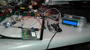
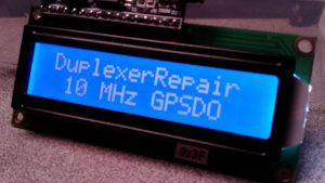
Left to right in this photo, are the GPS module and buffer board (sitting atop the breadboard which was used to initially design the buffer board circuitry), the Arduino Uno module, and the LCD display module, all interconnected and functioning. All of these will be assembled into a rack-mount unit.
Our GPSDO system, as seen in the photo as it was being assembled and tested here on one of the lab benches, consists of essentially four subassemblies, three of which are off-the-shelf items, and one module/board which was created right here in the lab:
Ublox Neo-M7M GPS Receiver module
Arduino Uno module
16×2 LCD Display module
Custom designed signal buffering/conditioning board
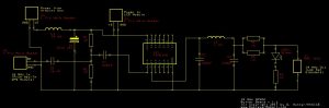
Once all of the off-the-shelf items were in hand, the task of designing and refining the special buffer board which takes the
Buffer Board schematic.
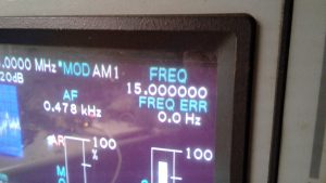
oscillator output from the GPS module (a square wave) and conditions and converts it to a usable sine wave at a very specific frequency took about a week (squeezing it in between other work.) This buffer board also provides impedance matching so that it can be connected to the instruments in the lab as a frequency standard, phase synchronization device, and calibration reference for radio equipment, frequency counters, and other instruments. Our final working prototype is not exactly the most aesthetically attractive looking thing in the world, but it sure does work well. How well? A good example can be seen in the following photograph showing that the IFR (running on the GPSDO system as a 10 MHz reference oscillator) indicates that WWV’s 15 MHz signal to be 15.000000 MHz with an error of 0.0 Hz.
The carrier frequency of WWV’s 15 MHz transmission out of Boulder, CO, as read by the IFR 1600 with our GPSDO connected as its frequency/oscillator reference.
Since we can only see one decimal place beyond the Hz digit in this example, the fact that the 1/10 of a Hz digit is rounding to the digit “0” means the value the IFR is coming up with must be in the range of -0.05 and +0.04 Hz, which equals a calculated maximum error of +/- 0.05 Hz. In the case of our 15 MHz frequency (15,000,000 Hz) that’s equivalent to an error of 0.00333 PPM (or 3.33 PPB, depending on which reference you prefer.) That is way better than the level of accuracy required for communications work. As an example, the FCC says that in land mobile radio equipment, the permissible carrier frequency error for a fixed transmitter operation in the range of 50-450 MHz is 5.0 PPM. Do a little math and you’ll see that our GPSDO has the IFR operating at roughly 1,500 times the level of accuracy required by the FCC rules. Sweet! Even sweeter is the fact that — unlike a rubidium frequency standard which has to be sent off for calibration once a year or so — our GPSDO is essentially updating its own calibration several times a second by constantly receiving the GPS signals and synchronizing itself. With an active gain GPS antenna attached, it rarely indicates being locked on less than 10 satellites simultaneously. It only takes four satellites to achieve a super-accurate “lock” but ours typically registers being locked on 11 and even 12 satellites. Did we mention that is with the antenna still inside the lab? Although it appears quite unnecessary, in the interest of maintaining the best lock and avoiding any potential interference to the GPS performance from equipment running here in the lab, we’re going to be installing an active, weatherproof, marine grade GPS antenna in an elevated position outside the lab. Another benefit of this GPSDO system is the fact it can achieve an accurate frequency lock in less than three seconds of power-up; whereas, rubidium standards employ temperature compensated ovens and typically have to be powered up for several hours for their oscillators to warm up before they stabilize and can be used as a reliable lab reference.
The icing on the cake in this recipe is the affordability of the project. Here’s a rough breakdown of the cost of creating this:
$15.30 — uBlox Neo-M7M GPS Module
$19.48 — Active GPS antenna and necessary adapters and cables
$5.45 — Arduino Uno (“knock-off”/compatible 3rd party clone)
$8.79 — 16×2 LCD Display with I2C interface module
>$10.00 — estimated cost of perf board, electronic components, etc. to build prototype “buffer board”
——————————————————
$59.02 — estimated final cost
That’s less than the one-way shipping cost of sending just the IFR analyzer off for calibration (and don’t even ask the actual cost of the calibration service — it’s astronomical.) With a hyper-accurate 0.00333 PPM frequency reference in-house, that’s exactly where the calibration work on our instruments will be done if/when needed.
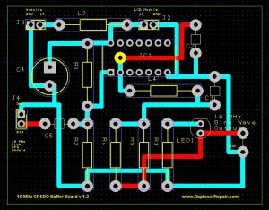
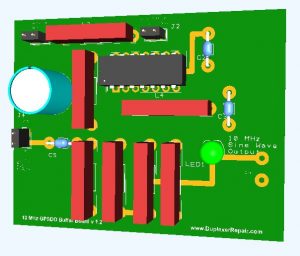
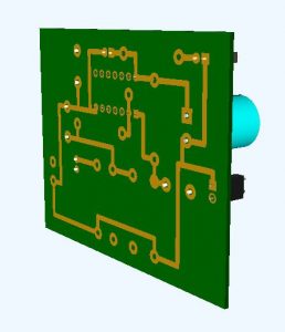
PCB layout design for the version 1.2 GPSDO Buffer Board.3D rendering of the v1.2 Buffer Board.3D rendering of the reverse side of the v1.2 Buffer Board.
A rework of the schematic and accompanying PCB layout have now been completed and we’ll soon be fabricating a nicely laid-out version 1.2 of the Buffer Board. Once we’ve fully assembled and tested that prototype board, we’re considering having several of the boards manufactured so that others who are interested in putting together a similar system can simply purchase one of our buffer boards and the parts to populate it (which we might offer in a kit form.) Estimated time to solder all the components is roughly 30 minutes to an hour, depending on how well versed you are with a soldering iron.) There might be a version 2.0 board in the works as well — using SMD components to further reduce the cost, board size, power consumption, and to reduce the amount of RF emission.
We’re seeing a spike in equipment coming in from Florida for tuning and repairs. The majority of it is “word-of-mouth” referrals, with some manufacturer referrals in there as well. Thank you all! It is indeed a pleasure to be of service to all of you and to provide you with top-notch repairs, tuning, and customer service.
We naturally get lots of telephone calls and emails asking how much we charge to tune duplexers and filters. In the interest of saving you time and getting your equipment in, tuned, and back to you even faster we have a new page on our website with “flat rate” pricing so you can quickly determine what the fees will be. Note that these prices apply only to equipment which arrives in our lab in good working order with all necessary cables, connectors, adapters, hardware, etc. attached. Just click on this link to see view our Flat Rate Tuning Service Price List. Quick turnaround. Precision work. Excellent customer service. All at prices quite friendly to your equipment and maintenance budget.


 Having accurately calibrated equipment here in the DuplexerRepair labs is a must, but sending instruments out to have them calibrated so that we know we’re calibrating and tuning your equipment accurately is very expensive. It also takes the equipment out of service if it has to be sent to an outside lab. Knowing that the ideal solution to keeping the equipment in service, accurately calibrated, and controlling costs would be to have an accurate in-house frequency standard, we decided to explore options such as calibrated rubidium oscillators, cesium driven units, etc.