[UPDATE (11/24/18)]
Several additions and modifications have been made to the development/beta version of this transmitter telemetry system over the
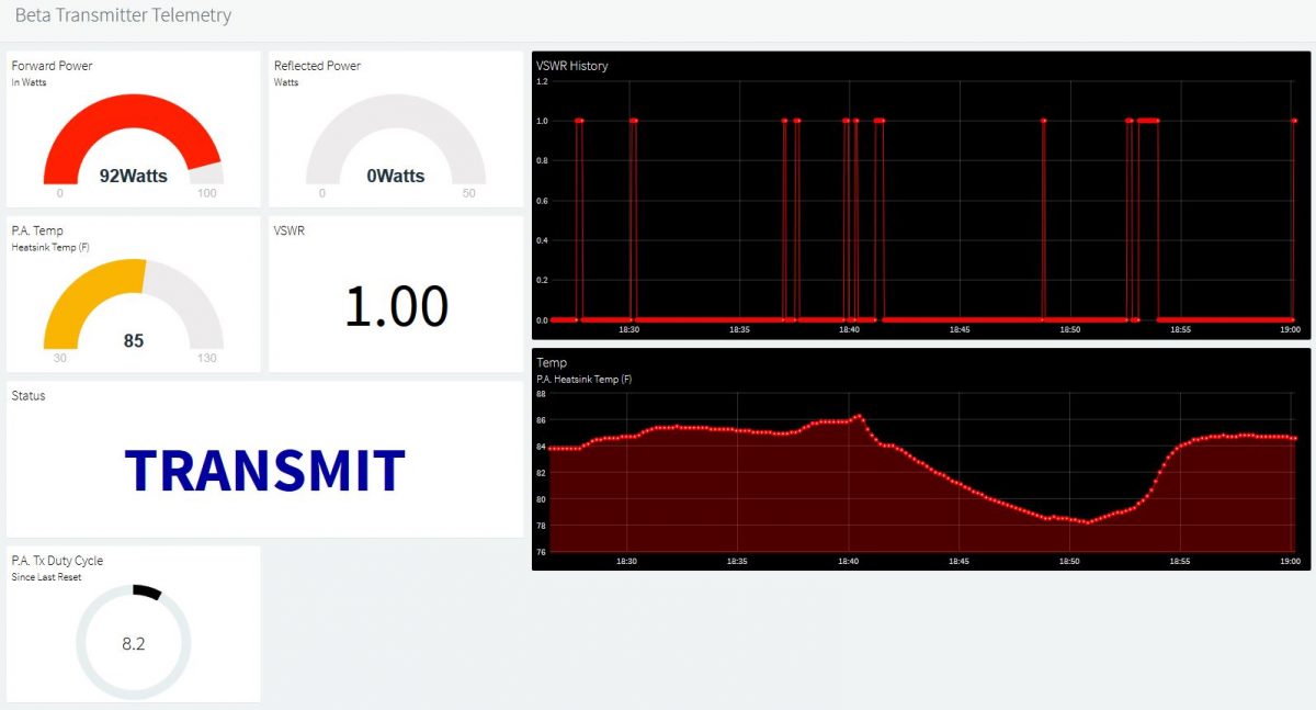
past couple of days. Keyline status monitoring has been added to the circuitry and code (indicating whether the transmitter is in “STANDBY” or “TRANSMIT” mode) which can be seen in real time on the updated dashboard, which has a few added features, including up to 24 hour graphing of the P.A. heatsink temperature, and P.A. duty cycle percentage display. As I mentioned before, this is a “work in progress” and the imagination is about the only limit to what I can build into this telemetry system.
————————————————–
[Original post] Having gotten the Power & SWR Monitor Panel with LCD display to a state that it’s ready to operate permanently on one of the paging transmitters
owned by a client, I’ve already begun developing the next generation of the project: an IoT based monitoring system which provides real-time monitoring of system performance.
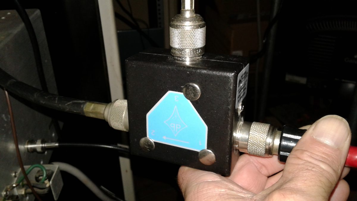
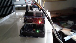
This generation of the project utilizes an Ethernet shield running on an Arduino Mega development board. It also has the added feature of temperature monitoring. The thermal probe is strapped to the back of the P.A. heatsink assembly for now. I plan to test locating the thermal probe inside the P.A. final stage cavity, but it remains to be seen whether the high level of RF inside the cavity may interfere with the circuitry which is actually located inside the working end of the probe.
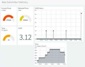
The system monitors and will remotely display forward RF power, reflected RF power, SWR/VSWR, and the heatsink temperature. I am considering adding monitoring of the “key” line. The purpose of doing that would be to be able to remotely determine whether a system malfunction (pages not being transmitted) was related to problems with the linking receiver system (which would result in no transmit “keying” of the other components in the system), keying with no or low P.A. output (most likely P.A. or exciter failure or malfunction), or high SWR (antenna or transmission line issues.) The latter two are already covered, but being able to narrow down a link receiver radio issue before even packing up for a service call could be very useful (one of those radios weighs about five pounds… if you’re familiar with Glenayre/Quintron equipment, then we don’t even need to talk about how much one of the Glenayre or Quintron power amplifiers weighs!)
Now, it’s time for coffee while I sit and ponder what cool things to do to this creation next. It is truly a work in progress.
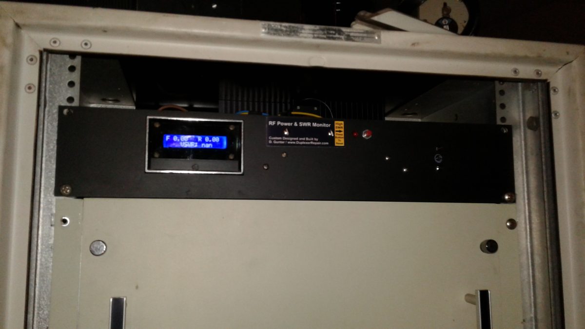
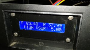 In the event of a high SWR event, the LCD display shows the actual VSWR and an audible alarm is activated. In addition, an SWR alarm LED turns on, which remains lit until a momentary contact button is pressed, resetting the alarm condition. I wrote the Arduino IDE sketch code to “latch” the LED so that in the event of a temporary high SWR event (ice on the antenna, for example) the system
 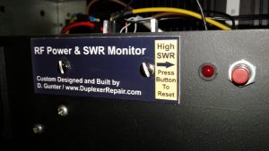 can continue to update and display real-time power and SWR readings but there will be a visible indication on the front panel that a temporary high SWR issue occurred.