This post could appropriately be subtitled “The Costs of Doing Good RF Business.” I’m a fan of Decibel Products duplexers because they do an excellent job in repeater applications. But like any piece of hardware, they are not immune to damage or failures. Many of Decibel Products’ duplexers (most notably the DB4060 and DB4062 VHF models) utilize precision trimmer capacitors which are the sort of component you love to hate.
On the plus side, the capacitors (commonly referred to as “Johanson capacitors, after the company which manufactured the bulk of the caps used) are known for the ability to be very precisely tuned, largely due to the fact that it takes around 20 turns of the capacitor’s adjusting screw to go from one end of its capacitance range to the other. Compare this to many open plate type capacitors which go through their full capacitance range in only 1/2 turn and it’s obvious that very accurate and precise tuning is much easier using the Johanson type capacitor; however, utilizing them in a duplexer cavity also makes the cavity a bit more prone to fail under certain conditions. That’s the trade-off involved.
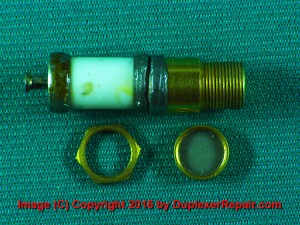
The very design elements which make the Johanson capacitors so great also make them much more fragile and more easily damaged. First of all, they are very small. The diameter of the outer ceramic cylinder of these capacitors is only 0.244” (6.20 mm to be more precise.) The component is hermetically sealed from the outside environment, which is good, because moisture and dust are enemies to such devices. At the same time, the very small enclosure size means that any heat in the device pretty much STAYS in the device until it dissipates through by conductive and convective methods — not always a fast process.
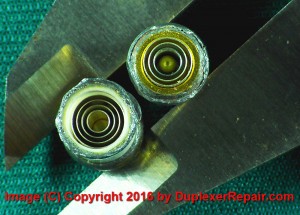
The actual capacitance creating part of these capacitors is a combination of concentric cylinders. One set of concentric cylinders is permanent attached to a stationary end inside the ceramic cylinder. A second set of cylinders is attached to the adjusting/tuning screw which has very, very fine pitched threads, giving the capacitor highly precise tuning ability because it takes so many turns to adjust it from one end of its range to the opposite end. As the screw is adjusted, this second set of metal cylinders moves in and out of the stationary set. If you’re familiar with electronics theory, you’ll recall that the two ways of varying the value of a capacitor (without altering the material used) is to either increase/decrease the size of the plates, or alter the spacing between the plates. A sort of combination of both variables has been accomplished in open-plate capacitors for ages by physically rotating one set of plates in and out of a second set in a horizontal fashion. This is the type of variable capacitor we see commonly used in everything from tiny transistor radios to the large open-plate variable capacitors used in high wattage antenna tuners/matchers. The difference in the Johanson capacitor’s operation is that they accomplish the same thing by changing how deeply the sets of concentric metal cylinders are meshed. They simply move in or out in a linear fashion.
The largest of the metal capacitor plate cylinders measures approximately 0.193″ (4.90 mm) outside diameter. Keep in mind that’s the LARGEST of the cylinders, which get increasing smaller in size, and there are seven total cylinders between the two sets. The smallest of the capacitive plate cylinders is approximately 0.063″ (1.60 mm) outside diameter. Metal objects this small can’t handle much heat, for starters. As those of us in the electronics and communications world all know, heat is not our friend. At the least, heat causes metals to expand. Given the miniscule size of these cylindrical capacitor plates, it wouldn’t take much heat to totally alter their size — thus the effective spacing between them — thereby changing the capacitance. These capacitors are used in the duplexer cavities to tune the rejection notch; therefore, if the capacitance changes, the notch tuning changes. If the notch tuning changes, the pass/reject performance of the cavity changes. In short, excessive heat buildup in the capacitor will cause the cavity and the duplexer set to fall below designed performance specifications. This obviously is not what we want happening.
What would cause excessive heat buildup? A number of factors contribute to heat in the capacitors. First, RF energy by its very nature produces some amount of heat. That’s unavoidable. Many of the repeaters built or serviced by DuplexerRepair.com operate upwards of 100-125 Watts maximum. The higher the power from the repeater’s power amplifier, the more heat is generated in the cabling, duplexer cavities, and most importantly in the capacitors and other “loop” components. While RF energy that’s flowing through the devices is just part of the process, there are other causes which aren’t part of normal repeater operation which can be downright catastrophic, especially to these fragile capacitors we’re discussing.
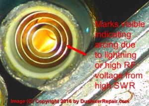
High SWR in the antenna and feedline system can cause abnormal amounts of RF energy that’s supposed to be leaving the antenna in the form of electromagnetic waves to actually reflect back down the feedline to the duplexers. Since these capacitors are intended to help block the unwanted frequency from getting through by essentially creating a short-circuit to ground (the cavity cylinder itself is grounded) any increase in RF through the capacitor means increased heat. If the heat becomes great enough, the tiny capacitor cylinders themselves can expand to the point that they make physical contact between cylinders, essentially creating an RF short-circuit to ALL RF energy (meaning the frequency that’s supposed to be getting blocked along with everything else.) This short-circuit only leads to more and more heat, and it is commonly a cause of power amplifier/transmitter damage and failures as well. The end result is a catastrophic failure. If your antenna is mistuned or has problems leading to increased SWR, your duplexers are more likely to fail because of damage to these capacitors. Likewise, feedline problems such as physical damage (or even poor grade cabling/feedline) can cause high SWR and eventual failure. Lastly, mistuning of a cavity — even relatively slight — means needlessly increased RF energy is hitting places and components where you don’t want it to. Tick, tock… it’s just a matter of time until trouble occurs.
There’s also our other enemy in the radio world: lightning. Let’s face it, there’s not much need for technical explanation of the effects of lightning here, because we know it’s just downright destructive to communications equipment, and if it directly strikes an antenna (or even in close proximity) even the highest quality lightning protection devices can only do so much. If a hundred or so watts of misdirected energy can damage one of these capacitors, just imagine what a few megawatts from a lightning strike will do in terms of destructive effects. Enough said about that.
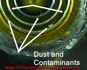
Dust particles and contaminants are theoretically kept out of these capacitors by sealing the plate cylinders inside the capacitor’s housing. The key word here is “theoretically.” Nothing is perfect. It only takes a few micron-sized particles of moisture or dust getting inside one of these capacitors to create a failure scenario. Moisture causes corrosion. Corrosion on the capacitive cylinders not only alters the capacitance but also creates potential conduction paths for electrical current which lead to RF short circuits. Dust particles similarly create unwanted conduction paths. Bottom line: we want to minimize any risk of contamination by moisture, dust, or other contaminant as much as
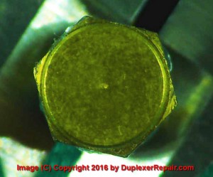
possible. They aren’t healthy for radio equipment, duplexer cavities, or these capacitors in particular. These capacitors come with protective screw-on sealing caps. They should be kept on the capacitors and fairly firmly tightened at all times, the only exception being while tuning is being performed on the duplexer assembly. Otherwise, moisture and micron sized particles of dust, etc. can and will eventually make their way between the tiny threads and into the capacitor, causing an eventual failure. Likewise, although it should not need to be pointed out: proper control of the ambient environment where the duplexers are installed is worth all the effort you put into it.
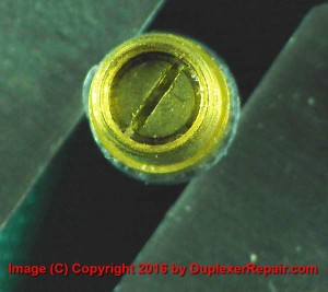
Something to watch for (or perhaps we should say “feel for”) if you’re tuning a set of duplexers which use these caps: very loose or tight feeling threads when turning the adjustment screw/slug. The screw should offer some/moderate resistance to being rotated for tuning; however, if it seems to spin pretty freely or feels as though it takes a lot of torque to turn it, the capacitor needs to be replaced. A loose turning adjustment screw usually means the capacitor is cracked (we’ve seen them broken completely into two halves, totally separated physically.) A tuning screw that feels excessively bound/tight typically means the capacitor has significant heat/lightning damage. In either case, you’ll only prolong the inevitable and end up “chasing your tail” trying to make the duplexers work properly and stay properly tuned and functioning. More often than not, Decibel Products duplexers we see in use by Amateur Radio folks are surplus/repurposed sets which had been used in commercial or public safety communications prior to being pulled out of service, eventually ending up in the hands of ham radio folks. We often suspect that the reason they were pulled from prior commercial/public safety use was due to… wait for it… failing capacitors which led to a two-way shop making the recommendation to just replace the whole set with new ones due to time constraints, and possibly because the radio shop can usually make more money selling a new set than they can by repairing the failed set. Plus, they often have to install another set immediately in order to get the system back in operation, so instead of the system being down twice it often makes more sense in those circles to just install new ones immediately. All that said, there’s probably a reason some ham got hold of the things for considerably less than the going price for new ones, and that reason is often undisclosed, unknown, and undetectable until attempts are made to actually put them to use in a repeater system. For those who have never done in-depth duplexer work, it’s worth mentioning that duplexers can often seem to work great when you’re testing and tuning them at power levels down in milliwatt/microvolt range but prove to be total garbage when you hit them with the sort of power levels coming out of a repeater’s transmitter. Experienced duplexer repair techs are better versed in things to look for which could spell trouble for duplexers in the real radio world.
There is another issue which can contribute to failure of these capacitors which should be pointed out: improper installation of the capacitors in the duplexer cavities. The capacitors most commonly used in the design of Decibel Products duplexers are attached to the cavity loop assembly by means of a stud/pin on the end of the capacitor which is soldered to the copper resonating loop. The opposing end is attached to the loop enclosure by means of a retaining nut. Because they are very easily damaged by heat, it’s extremely critical that the temperature and soldering time be precisely controlled. Not enough heat when soldering the capacitor in place will result in a poor solder connection (cold solder joint) which will have added resistance (heat buildup from RF current) or can open entirely, causing the cavity to fail. Too much heat during soldering will either destroy the capacitor immediately (and these things are not cheap) or do damage which will shorten the life of the capacitor tremendously. Proper installation of the retaining nut on the end of the capacitor which protrudes through the loop enclosure is also important. Too tight and the capacitor can be deformed and damaged. Too loose and the contact (conduction path) can be poor, plus the entire capacitor assembly may try to spin during adjusting, which can in turn break the capacitor assembly (if the solder joint at the other end is nice and strong) or torque the loop, resulting in deformation, pass frequency shifting, and a loop which might try to slowly move back into its proper shape (usually well after you’ve reinstalled the duplexers and left the repeater site) causing everything to go haywire — which Mr. Murphy delights in seeing happen at the most inopportune times. Decibel Products typically painted the loop enclosures AFTER installing the components including these capacitors. Some people complain about that making it more difficult to remove that tiny, ultra-fine threaded retaining nut. Don’t be a hater: by doing so they actually reduced the chances of the nut working loose and allowing things to move around which should be doing so. Kudos to Decibel for that decision. It’s not uncommon for the retaining nuts to bend, break, and generally become unrecognizable (not to mention unusable) when they have to be removed. That’s okay, because we only remove them to repair a loop enclosure (or modify it for operation at a different frequency range than it was originally manufactured for by fabricating replacement loops of the proper length for the desired frequency range.) If we break the nut, we’ll replace it, and it’s not uncommon for the entire capacitor to already be in need of replacement during the conversion. If we see signs of heat damage (such as discoloration on the ceramic enclosure) the capacitor will be replaced. At DuplexerRepair.com we are extremely careful and diligent when inspecting and installing these capacitors because we want you to get the longest possible life and best performance out of any equipment we repair or recondition. This in turn helps to minimize the risk of damage/failure of the other equipment in your communications system, such as your receivers, exciters, and power amplifiers.
By now you probably know more than you ever imagined you would (or wanted to) about the precision capacitors used in Decibel Products duplexer cavities. We just thought you deserved to be well informed of the pros, cons, and factors you should take into consideration regarding certain Decibel Products duplexers because of the capacitors used. We do highly recommend these duplexers because their design is excellent, their performance is fantastic, and the lifespan of Decibel Products duplexers between repairs/overhauls is wonderful, provided they — and the rest of your communications system — are installed and maintained properly. While we can’t control when and where lightning strikes will occur and cause damage to equipment, we can reduce the chances of system failures through proper attention to the details we do have some control over.
If you are the owner of a set of these Decibel Products duplexers and you need tuning, repair, conversion, or complete overhaul/refurbishing of a set, get in touch with us by calling (334) 787-9005 or by emailing service@duplexerrepair.com. We’ll have them in proper working order and back to you as quickly as possible (usually within 2-3 days, although sometimes it takes a bit longer, especially if parts/cables have to be fabricated or special-ordered.)